background image

5

Verifying the Hydraulic Top
Link Set Up

No Parts Required

Procedure

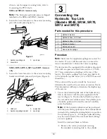
Extending the hydraulic cylinder will increase the
tine depth.

Fully extend the hydraulic cylinder to determine
the location of the tine heads and to verify if they
contact the ground.

CAUTION

If the tine heads contact the ground, turf
damage may occur.

Note:

On undulating turf, the operator can adjust

the cylinder to maintain tine depth (cresting a hill)
but it will be necessary to have the tine heads set
about 2 inches below ground.

If the tine heads contact the ground, adjust the
location of the cylinder ends to move the top of the
aerator closer to the tractor.

If the tine heads do not contact the ground,
extension brackets (included with aerator) can be
installed to the top link to move the tine heads closer
to the ground.

Important:

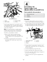
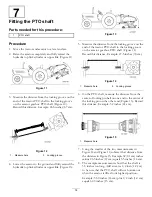
When connecting the PTO, be sure

that the aerator is not being lifted higher than is
necessary. Lifting the machine too high will cause
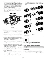
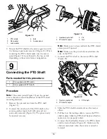
the PTO shaft knuckles to break (Figure 10). 
Never
leave the PTO turning when the aerator is lifted.
The PTO can be operated up to an angle of 25º, but
can never exceed a 35º angle when the aerator is
at its highest position or severe shaft damage may
occur.

Figure 10

1.

Breakage will occur here

6

Checking the PTO Angle

No Parts Required

Procedure

Important:

Make sure the tines are removed before

performing this operation.

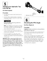
With the aerator positioned on the ground and lowered
to the deepest location, check the angle between the
PTO and the aerator.

Lift the aerator and fully retract the hydraulic top link
cylinder. Using an angle indictor, check the angle
between the PTO and the aerator. If this angle is greater
than 35 degrees, make adjustments to the tractor so
that the aerator cannot be lifted past 35 degrees. This
can be accomplished by using the tractor lift stop (if
so equipped) or moving the lower links to a higher
mounting hole (if so equipped).

13

Summary of Contents for procore sr48

Page 1: ...00001 and Up Model No 09932 Serial No 311000001 and Up Model No 09933 Serial No 311000001 and Up Model No 09934 Serial No 311000001 and Up Model No 09935 Serial No 311000001 and Up Model No 09936 Seri...

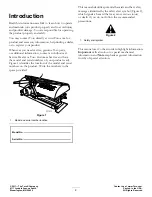
Page 2: ...entifies the location of the model and serial numbers on the product Write the numbers in the space provided Figure 1 1 Model and serial number location Model No Serial No This manual identifies poten...

Page 3: ...emoving the Storage Stands Models SR48 and SR72 21 Product Overview 22 Specifications 22 Attachments Accessories 22 Operation 23 Tractor Controls 23 Principles of Operation 23 Tractor PTO Speed 23 Tra...

Page 4: ...ennis shoes sneakers or shorts Also do not wear loose fitting clothing which could get caught in moving parts Always wear long pants and substantial shoes Wearing safety glasses safety shoes hearing p...

Page 5: ...on the aerator switch off the engine stop the PTO and apply the parking brake before dismounting from the tractor Be sure the aerator is on the ground or lowered onto the safety stands Support the mac...

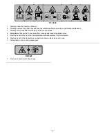
Page 6: ...drive 100 3612 1 Entanglement hazard stay away from moving parts keep all guards and shields in place 110 4668 1 Entanglement hazard shaft stay away from moving parts 2 PTO speed and input direction...

Page 7: ...erate this machine unless you are trained 4 Entanglement hazard belt stay away from moving parts keep all guards in place 5 Crushing hazard of hand or foot keep bystanders a safe distance from the mac...

Page 8: ...4 Lynch pin 3 Connect Upper Link Models SR54 S and SR70 S 5 No parts required Verify the top link set up 6 No parts required Checking the PTO angle 7 PTO shaft 1 Fitting the PTO shaft 8 PTO Shield 1...

Page 9: ...aerator from the pallet 3 Remove the storage stands from the aerator Retain them for storage use Note The SR54 S and the SR70 S do not have shipping stands 4 Place the aerator on a flat level surface...

Page 10: ...couplings The tractor must be equipped with a double acting spool valve with an operator control lever and two 1 2 inch 12 7 mm quick release couplings at the rear of the tractor Two quick couplings...

Page 11: ...lings to the hydraulic hoses 1 2 14 NPTF hose end thread size Apply Teflon tape or pipe thread sealant to the hose threads to prevent any leaks 5 Connect the two hydraulic hose quick couplings to the...

Page 12: ...y removed Figure 5 4 Connecting the Tractor Upper Link Models SR54 S and SR70 S Parts needed for this procedure 1 Spring loaded top link 3 Link pin 3 Lynch pin Procedure 1 Mount the spring loaded top...

Page 13: ...e aerator is not being lifted higher than is necessary Lifting the machine too high will cause the PTO shaft knuckles to break Figure 10 Never leave the PTO turning when the aerator is lifted The PTO...

Page 14: ...tractor PTO shaft to the locking groove on the aerator gearbox PTO shaft Figure 14 Record this distance Example 27 5 inches 70 cm Figure 14 1 Measure here 2 Locking groove 6 On the PTO shaft measure...

Page 15: ...om each PTO half Figure 17 illustrations 2 3 Note More will have to be cut off the inside tube if it was protruding into the cross and bearing section of the outer tube 14 Using the dimensions determi...

Page 16: ...lutch end of the PTO shaft to the aerator gearbox input shaft with pin and nut previously removed Figure 19 The pin can only be inserted one way Figure 19 1 Gearbox input shaft 3 Pin 2 PTO shaft coupl...

Page 17: ...he aerator is lifted The PTO can be operated up to an angle of 25 but can never exceed a 35 angle when the aerator is at its highest position 7 Verify that the PTO shield does not interfere with the c...

Page 18: ...le for the aerator Choose the tine type size and spacings required for the job Refer to the Parts Catalog for the list of accessories 1 Make certain the aerator is fully supported on the stands or sup...

Page 19: ...Installing the Rear Guard Parts needed for this procedure 1 Rear guard 4 Screw 3 8 x 3 1 4 inch 12 Flat washer 438 x 1 00 inch 4 Lock nut 2 End cap Procedure 1 Insert the end caps into the ends of th...

Page 20: ...latch while aligning the mounting hole with the hole in the side plate Figure 30 Figure 30 1 Retaining ring 3 Latch plate 2 Mounting hole 4 Tap bolt 2 Secure the latch plate to the side plate with a...

Page 21: ...2 Remove the bolts and nuts securing the storage stands to each end of the aerator Figure 32 Figure 32 1 Bolts 3 Nut 2 Lock washer 4 Storage stand 3 Remove the storage stands 4 Use the storage stands...

Page 22: ...t hr 3 530 sq m hr 48 000 sq ft hr 4 460 sq m hr Recommended Tractor Size 25 HP 16 18 HP 18 HP 25 35 HP 25 35 HP 45 HP 55 HP Recommended Lift Capacity 1 800 lbs 817 kg 1 200 lbs 544 kg 1 500 lbs 680 k...

Page 23: ...rpm PTO by calculating as follows Engine rpm at 540 PTO speed x 400 540 required engine rpm For example if the engine rpm were 2700 for a PTO speed of 540 rpm you would get 2700 x 400 540 2000 rpm In...

Page 24: ...in reverse 9 Always clear the area of all damaged machine parts such as broken tines etc to prevent anything from being picked up by mowers or other turf maintenance equipment and thrown 10 Replace b...

Page 25: ...te again at a deeper penetration Aeration of soil types built on top of hard sub soils i e sand soil cap placed over rocky ground can cause undesired hole quality This is caused when the aeration dept...

Page 26: ...stment holes in the camber bracket Figure 34 Figure 34 1 Camber bracket 5 10 inch tine 2 16 inch tine 6 14 inch tine 3 12 inch tine 7 Tine head pivot bolt 4 7 inch tine 8 Spring 5 Rotate the camber br...

Page 27: ...nch tine 7 14 inch tine 4 16 inch tine 8 Spring 4 Remove the nut and bolt in the adjustment holes in the camber bracket Figure 36 5 Rotate the camber bracket until it is aligned with the desired hole...

Page 28: ...sh may be used to remove caked on material Use mild detergent to clean the covers After cleaning grease all drive lines and roller bearings inspect for machine damage oil leakage component and tine we...

Page 29: ...lean tines Remove all debris Yearly Adjust the PTO clutch Before and after storage Lifting the Machine CAUTION When changing attachments or performing other service use correct blocks hoists or jacks...

Page 30: ...aring condition and seal integrity should be conducted to avoid downtime These bearings should be inspected seasonally and replaced if damaged or worn Bearings should operate smoothly with no detrimen...

Page 31: ...Fill the gear box with high quality 80W 90 gear lube Use the following chart to determine the gear box oil capacity Model Gear Case Capacity SR48 2 quarts 1 9 liters SR54 2 quarts 1 9 liters SR54 S 2...

Page 32: ...1 Clutch nut 2 Clutch 2 At the start of the new season start the PTO and allow the clutch to slip for a few seconds before stopping the PTO Turn back the nuts an additional 2 turns Note Do not allow t...

Page 33: ...oller s 3 6 inches off ground Place support blocks under the roller s 4 Stop the engine and remove the key from ignition switch 5 Before leaving the Operator s seat on tractor wait for engine and all...

Page 34: ...in the head Tighten the tine holder bolts do not use jam nuts or impact wrench If the bolt will not hold the tine replace it Tines pull the soil up when the machine is raised Raise the machine part o...

Page 35: ...ine fastener screw threads 5 Store the machine on the provided storage stands on a hard dry surface 6 Loosen the PTO clutch bolts two turns 7 Connect the PTO safety chain to the aerator in stored posi...

Page 36: ...be outside influence include but are not limited to weather storage practices contamination use of unapproved coolants lubricants additives fertilizers water or chemicals etc Normal noise vibration we...

Reviews: