background image

Greasing the Bearings

Service Interval:

Every 50 hours

The main working bearings of the aerator are sealed and
require no maintenance or lubrication. This drastically
reduces the maintenance required and eliminates the risk
of grease or oil being dropped onto the turf.

There are grease fittings that must be lubricated with
an SAE multi purpose, high-temperature grease with
high pressure (EP) performance or SAE multi purpose
lithium base grease.

The lubrication points are:

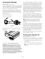
PTO Shaft (3) (Figure 39)

Figure 39

Roller bearings (Qty. 2 or 4, depending on model)
(Figure 40)

Figure 40

O-ring chain —

Do not lubricate the chain.

Important:

Bearings rarely fail from defects in

materials or workmanship. The most common
reason for failure is moisture and contamination
working its way past the protective seals. Bearings
that are greased will rely upon regular maintenance
to purge harmful debris from the bearing area.
Sealed bearings rely on an initial fill of special grease
and a robust integral seal to keep contaminants and
moisture out of the rolling elements.

The sealed bearings require no lubrication or short term
maintenance. This minimizes routine service required
and reduces the potential of turf damage due to grease
contamination. These sealed bearing packages will
provide good performance and life under normal use,
but periodic inspections of bearing condition and seal
integrity should be conducted to avoid downtime. These
bearings should be inspected seasonally and replaced if
damaged or worn. Bearings should operate smoothly
with no detrimental characteristics such as high heat,
noise, looseness or rust weeping.

Due to the operating conditions these bearing/seal
packages are subject to (i.e. sand, turf chemicals, water,
impacts, etc.) they are considered normal wear items.
Bearings that fail due to other than defects in materials or
workmanship are typically not covered under warranty.

Note:

Bearing life can be negatively affected by

improper wash down procedures. Do not use
high-pressure or high volume spray directly at the
bearings.
It is common for new bearings to purge some grease out
the seals on a new unit. This purged grease will turn
black in color due to collection of debris and not due to
excessive heat. It is good practice to wipe this excess
grease from the seals after the initial 8 hours. There may
always appear to be a wet area around the seal lip. This
is generally not detrimental to bearing life, but keeps
the seal lip lubricated.
Inspect the coring head bearings every 500 operating
hours and replace as needed.

Checking the Gearbox Oil

Service Interval:

Every 50 hours

The gearbox is filled with 80W–90 gear oil or equivalent.
Allow the gear box to cool before checking the oil level.

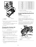
1. Clean debris from fill plug and check plug to avoid

contamination.

2. Remove the check plug from the gearbox (Figure 41).

Note:

If the gearbox has two check plugs, use the

bottom one.

30

Summary of Contents for procore sr48

Page 1: ...00001 and Up Model No 09932 Serial No 311000001 and Up Model No 09933 Serial No 311000001 and Up Model No 09934 Serial No 311000001 and Up Model No 09935 Serial No 311000001 and Up Model No 09936 Seri...

Page 2: ...entifies the location of the model and serial numbers on the product Write the numbers in the space provided Figure 1 1 Model and serial number location Model No Serial No This manual identifies poten...

Page 3: ...emoving the Storage Stands Models SR48 and SR72 21 Product Overview 22 Specifications 22 Attachments Accessories 22 Operation 23 Tractor Controls 23 Principles of Operation 23 Tractor PTO Speed 23 Tra...

Page 4: ...ennis shoes sneakers or shorts Also do not wear loose fitting clothing which could get caught in moving parts Always wear long pants and substantial shoes Wearing safety glasses safety shoes hearing p...

Page 5: ...on the aerator switch off the engine stop the PTO and apply the parking brake before dismounting from the tractor Be sure the aerator is on the ground or lowered onto the safety stands Support the mac...

Page 6: ...drive 100 3612 1 Entanglement hazard stay away from moving parts keep all guards and shields in place 110 4668 1 Entanglement hazard shaft stay away from moving parts 2 PTO speed and input direction...

Page 7: ...erate this machine unless you are trained 4 Entanglement hazard belt stay away from moving parts keep all guards in place 5 Crushing hazard of hand or foot keep bystanders a safe distance from the mac...

Page 8: ...4 Lynch pin 3 Connect Upper Link Models SR54 S and SR70 S 5 No parts required Verify the top link set up 6 No parts required Checking the PTO angle 7 PTO shaft 1 Fitting the PTO shaft 8 PTO Shield 1...

Page 9: ...aerator from the pallet 3 Remove the storage stands from the aerator Retain them for storage use Note The SR54 S and the SR70 S do not have shipping stands 4 Place the aerator on a flat level surface...

Page 10: ...couplings The tractor must be equipped with a double acting spool valve with an operator control lever and two 1 2 inch 12 7 mm quick release couplings at the rear of the tractor Two quick couplings...

Page 11: ...lings to the hydraulic hoses 1 2 14 NPTF hose end thread size Apply Teflon tape or pipe thread sealant to the hose threads to prevent any leaks 5 Connect the two hydraulic hose quick couplings to the...

Page 12: ...y removed Figure 5 4 Connecting the Tractor Upper Link Models SR54 S and SR70 S Parts needed for this procedure 1 Spring loaded top link 3 Link pin 3 Lynch pin Procedure 1 Mount the spring loaded top...

Page 13: ...e aerator is not being lifted higher than is necessary Lifting the machine too high will cause the PTO shaft knuckles to break Figure 10 Never leave the PTO turning when the aerator is lifted The PTO...

Page 14: ...tractor PTO shaft to the locking groove on the aerator gearbox PTO shaft Figure 14 Record this distance Example 27 5 inches 70 cm Figure 14 1 Measure here 2 Locking groove 6 On the PTO shaft measure...

Page 15: ...om each PTO half Figure 17 illustrations 2 3 Note More will have to be cut off the inside tube if it was protruding into the cross and bearing section of the outer tube 14 Using the dimensions determi...

Page 16: ...lutch end of the PTO shaft to the aerator gearbox input shaft with pin and nut previously removed Figure 19 The pin can only be inserted one way Figure 19 1 Gearbox input shaft 3 Pin 2 PTO shaft coupl...

Page 17: ...he aerator is lifted The PTO can be operated up to an angle of 25 but can never exceed a 35 angle when the aerator is at its highest position 7 Verify that the PTO shield does not interfere with the c...

Page 18: ...le for the aerator Choose the tine type size and spacings required for the job Refer to the Parts Catalog for the list of accessories 1 Make certain the aerator is fully supported on the stands or sup...

Page 19: ...Installing the Rear Guard Parts needed for this procedure 1 Rear guard 4 Screw 3 8 x 3 1 4 inch 12 Flat washer 438 x 1 00 inch 4 Lock nut 2 End cap Procedure 1 Insert the end caps into the ends of th...

Page 20: ...latch while aligning the mounting hole with the hole in the side plate Figure 30 Figure 30 1 Retaining ring 3 Latch plate 2 Mounting hole 4 Tap bolt 2 Secure the latch plate to the side plate with a...

Page 21: ...2 Remove the bolts and nuts securing the storage stands to each end of the aerator Figure 32 Figure 32 1 Bolts 3 Nut 2 Lock washer 4 Storage stand 3 Remove the storage stands 4 Use the storage stands...

Page 22: ...t hr 3 530 sq m hr 48 000 sq ft hr 4 460 sq m hr Recommended Tractor Size 25 HP 16 18 HP 18 HP 25 35 HP 25 35 HP 45 HP 55 HP Recommended Lift Capacity 1 800 lbs 817 kg 1 200 lbs 544 kg 1 500 lbs 680 k...

Page 23: ...rpm PTO by calculating as follows Engine rpm at 540 PTO speed x 400 540 required engine rpm For example if the engine rpm were 2700 for a PTO speed of 540 rpm you would get 2700 x 400 540 2000 rpm In...

Page 24: ...in reverse 9 Always clear the area of all damaged machine parts such as broken tines etc to prevent anything from being picked up by mowers or other turf maintenance equipment and thrown 10 Replace b...

Page 25: ...te again at a deeper penetration Aeration of soil types built on top of hard sub soils i e sand soil cap placed over rocky ground can cause undesired hole quality This is caused when the aeration dept...

Page 26: ...stment holes in the camber bracket Figure 34 Figure 34 1 Camber bracket 5 10 inch tine 2 16 inch tine 6 14 inch tine 3 12 inch tine 7 Tine head pivot bolt 4 7 inch tine 8 Spring 5 Rotate the camber br...

Page 27: ...nch tine 7 14 inch tine 4 16 inch tine 8 Spring 4 Remove the nut and bolt in the adjustment holes in the camber bracket Figure 36 5 Rotate the camber bracket until it is aligned with the desired hole...

Page 28: ...sh may be used to remove caked on material Use mild detergent to clean the covers After cleaning grease all drive lines and roller bearings inspect for machine damage oil leakage component and tine we...

Page 29: ...lean tines Remove all debris Yearly Adjust the PTO clutch Before and after storage Lifting the Machine CAUTION When changing attachments or performing other service use correct blocks hoists or jacks...

Page 30: ...aring condition and seal integrity should be conducted to avoid downtime These bearings should be inspected seasonally and replaced if damaged or worn Bearings should operate smoothly with no detrimen...

Page 31: ...Fill the gear box with high quality 80W 90 gear lube Use the following chart to determine the gear box oil capacity Model Gear Case Capacity SR48 2 quarts 1 9 liters SR54 2 quarts 1 9 liters SR54 S 2...

Page 32: ...1 Clutch nut 2 Clutch 2 At the start of the new season start the PTO and allow the clutch to slip for a few seconds before stopping the PTO Turn back the nuts an additional 2 turns Note Do not allow t...

Page 33: ...oller s 3 6 inches off ground Place support blocks under the roller s 4 Stop the engine and remove the key from ignition switch 5 Before leaving the Operator s seat on tractor wait for engine and all...

Page 34: ...in the head Tighten the tine holder bolts do not use jam nuts or impact wrench If the bolt will not hold the tine replace it Tines pull the soil up when the machine is raised Raise the machine part o...

Page 35: ...ine fastener screw threads 5 Store the machine on the provided storage stands on a hard dry surface 6 Loosen the PTO clutch bolts two turns 7 Connect the PTO safety chain to the aerator in stored posi...

Page 36: ...be outside influence include but are not limited to weather storage practices contamination use of unapproved coolants lubricants additives fertilizers water or chemicals etc Normal noise vibration we...

Reviews: