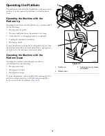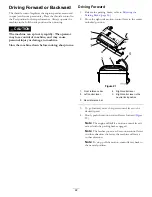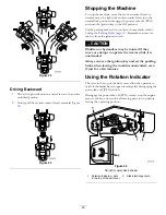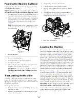
The Safety-Interlock System
CAUTION
If safety-interlock switches are disconnected or
damaged the machine could operate unexpectedly
causing personal injury.
•
Do not tamper with the interlock switches.
•
Check the operation of the interlock switches
daily and replace any damaged switches before
operating the machine.
Understanding the Safety-Interlock
System
The safety-interlock system is designed to prevent the mower
blades from rotating unless:
•
The right side motion-control lever is moved to the
center, unlocked position.
•
The blade-control switch (PTO) is pulled
on
.
The safety-interlock system is designed to stop the mower
blades if you move or release the right side motion-control
lever into the neutral-lock position.
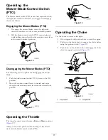
The hour meter has symbols to notify the user when the
interlock component is in the correct position. When the
component is in the correct position, a triangle will light
up in the corresponding square.
Figure 19
1.
Triangles light up when the interlock components are in the
correct position
Testing the Safety-Interlock System
Service Interval:
Before each use or daily
Test the safety-interlock system before you use the machine
each time.
Note:
If the safety system does not operate as described
below, have an Authorized Service Dealer repair the safety
system immediately.
1.
Start the engine; refer to
.
2.
Set the parking brake.
3.
Move the right side motion-control lever to the center,
unlocked position.
Note:
The blades should not rotate.
4.
Move the motion-control levers forward.
Note:
The engine should stop running.
5.
Start the engine and release the parking brake.
6.
Move the right side motion-control lever to the center,
unlocked position.
7.
Continue holding the right side motion-control lever
in the center, unlocked position, pull up on the
blade-control switch (PTO), and release.
Note:
The clutch should engage and the mower
blades rotate.
8.
Move or release the right side motion-control lever into
the neutral-lock position.
Note:
The blades should stop rotating and the engine
continues to run.
9.
Push the blade-control switch down and move the
right side motion-control lever to the center, unlocked
position.
10.
Continue holding the right side motion-control lever
in the center, unlocked position, pull up on the
blade-control switch (PTO), and release.
Note:
The clutch should engage and the mower
blades rotate.
11.
Push the blade-control switch (PTO) down to the Off
position.
Note:
The blades should stop rotating.
12.
With the engine running, pull up the blade-control
switch (PTO) and release it without holding right side
motion-control lever to the center, unlocked position.
Note:
The blades should not rotate.
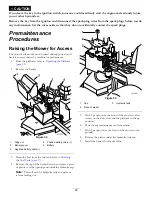
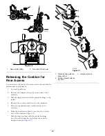
WARNING
The operator platform is heavy and may cause
injury when lowering and raising the operator
platform. The platform may suddenly drop if not
supported when the latch pin is pulled out.
•
Do not put your hands or fingers in the
platform-pivot area when lowering or raising the
operator platform.
•
Make sure the platform is supported when the
latch pin is pulled out.
•
Make sure the latch secures the platform when
folding it in the up position. Push it tight against
the cushion for the latch pin to lock into place.
•
Keep bystanders away when raising or lowering
the platform.
20
Summary of Contents for GrandStand 74574
Page 65: ...g026979 Electrical Schematic Rev A 65 ...
Page 66: ...Notes 66 ...
Page 67: ...Notes 67 ...


