Engine Maintenance
Checking the Engine Overheat
Warning System
Service Interval:
Every 500 hours
1
G014437
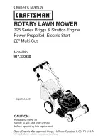
Figure 49
1.
Temperature switch
1.
Turn the ignition key to the ignition on position I.
2.
Disconnect the red/blue wire terminal from the
engine-temperature switch.
3.
Touch the metal terminal of this wire onto a suitable
earth point, ensuring that the metal surfaces make
good contact.
The horn sounds and the engine-coolant-temperature-warning
light illuminates to confirm correct operation. If the system is
malfunctioning, make repairs before operating the mower.
Servicing the Air Cleaner
Service Interval:
Before each use or daily
Every 500 hours
Servicing the Primary Air Filter
Check the air-cleaner body for damage which could cause an
air leak. Replace if damaged. Check the whole intake system
for leaks, damage or loose hose clamps.
Service the primary air-cleaner filter only when the service
indicator (
) requires it. Changing the air filter before
it is necessary only increases the chance of dirt entering the
engine when the filter is removed.
Important:
Be sure that the cover is seated correctly
and seals with the air-cleaner body.
1.
Check the filter-blockage indicator. If the indicator
is red, the air filter needs to be cleaned or replaced
(
).
G014565
Figure 50
2.
Before removing the filter, use low pressure air (40 psi,
clean and dry) to help remove large accumulations of
debris packed between outside of the filter and the
canister.
Avoid using high-pressure air which could
force dirt through the filter into the intake tract.
Note:
This cleaning process prevents debris from
migrating into the intake when the filter is removed.
1
2
3
g022394
Figure 51
1.
Rubber outlet valve
3.
Air filter
2.
Removable cover
3.
Remove the cover from the air-cleaner body.
4.
Remove and replace the filter (
).
Cleaning of the used element is not recommended due
to the possibility of damage to the filter media.
5.
Inspect the new filter for shipping damage, checking
the sealing end of the filter and the body.
Do not use
a damaged element.
6.
Insert the new filter by applying pressure to the outer
rim of the element to seat it in the canister.
Do not
apply pressure to the flexible center of the filter.
7.
Clean the dirt ejection port located in the removable
cover. Remove the rubber outlet valve from the cover,
clean the cavity and replace the outlet valve.
8.
Install the cover orienting the rubber outlet valve in a
downward position—between approximately 5 o’clock
to 7 o’clock when viewed from the end.
9.
Check the condition of the air-cleaner hoses.
10.
Secure the cover.
39