


The values can be set in the following ranges:
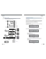
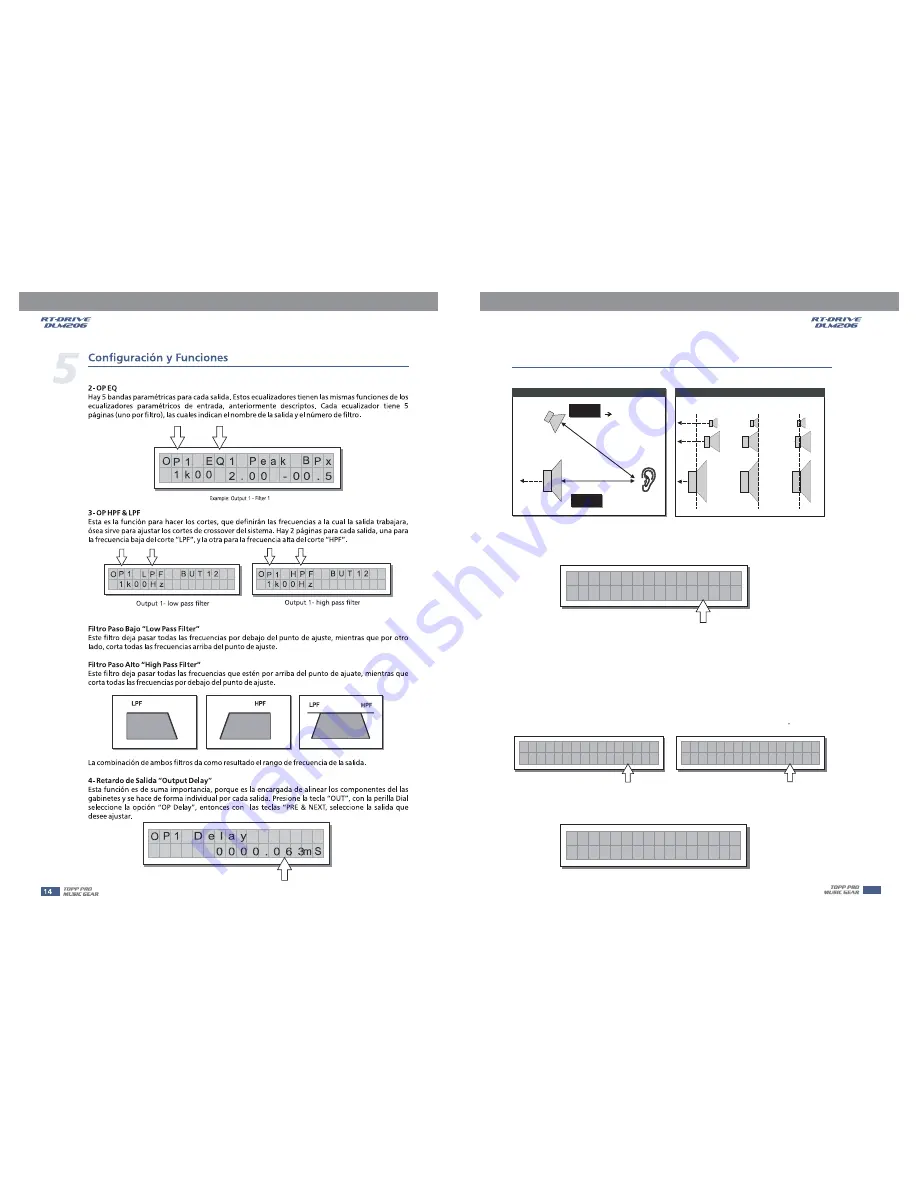
OUTPUT DELAY
Components
Loudspeaker
Alignment #1
Delayed Virtual
Alignment #2
Delayed Virtual
OUTPUT DELAY
OUTPUT DELAY
OUTPUT 1
HIGH
OP1 DELAY=
0ms
18ms(6 5m)
14ms(5m)
OP3 DELAY=
4ms
OUTPUT 3
LOW
4ms
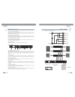
5) Output Gain
Output level control. Allows to adjust the signal level of each individual output.Editing valuesare between
+12dB ~ - 40dB, with 0.5dB steps.
O P 1
- 6 . 5
G a i n
d B
Note:
OUTPUT LEVEL LED
CLIP LED
LIMITER
LIMITER
The level of each output is shown by the respective
meter. To avoid distortion,
don't Let the red
lights up. As automatic protection, you can also enable the
(EDIT
menu) on the outputs that require it. In this case, remember that enabling the LIMITER changes the
display mode on the relative LED meter: in fact, the level shown is no longer the absolute output level,
but the level of the signal in relation to the
threshold.
C
onfiguration & Functions
5
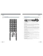
6) Output Pol
Controls the output's polarity. Allows to invert the phase of the signal of individual outputs.
Press
key, use
to adjust output polarity as shown in following
OUT
DIAL
Normal: leaves the phase unchanged
O P 1
N o r m
P O L A
a I
R I T Y
Reverse: shifts the phase through 180 , inverting it.
O P 1
e v e r
P O L A
s e
R I T Y
R
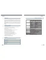
7) Output CompLim
Allows to keep the signal of each individual output within a set level, which can be used effe-
ctively to protect the components of a sound system.
O
0 0 3 / 0 0 4 m
C o m p L
1 : 0 3
- 0 2 . 0
P 1
i m
S
15