GTalarm3 User manual V-2022-05-24
24 |
E N
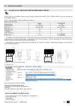
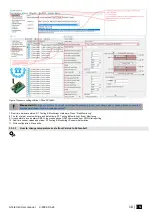
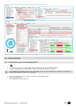
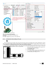
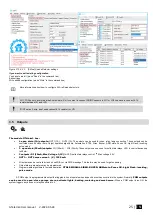
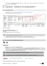
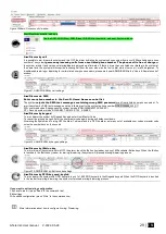
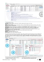
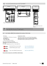
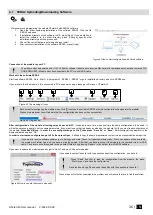
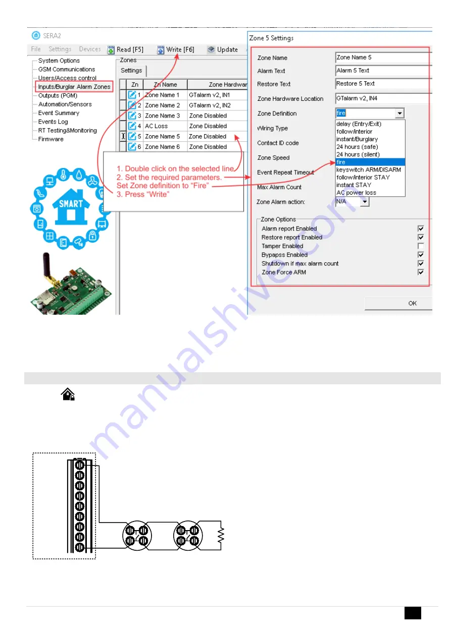
Figure 25[4-Wire] Smoke detector settings
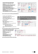
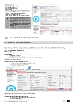
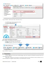
If you want to edit existing configuration
,
You have to read it (press “Read” in the command line)
Edit settings
Write edited configuration (press “Write” in the command line)
3.4.2.3
[2-Wire] Smoke Detector Wiring to I/O Inputs
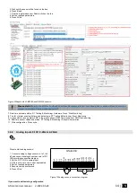
The 2-wire Smoke zone on the module is the only zone in the system that can have 2-wire smoke detectors as Fire Alarm initiating devices. This zone
is an end-of-line EOL 2.2K resistor type and can accommodate up to 30 compatible 2-wire smoke detectors. The zone is fixed as a 2-wire smoke zone.
I/O 2-wire smoke zone is trouble supervised zone. The zone wiring is supervised by the control panel.
The parameters of the zone should be defined as a “Fire Zone”. I/O1 and I/O2 can be defined as a 2-wire smoke detector input if a line short occurs
or the smoke detector activates, wheth
er the system is armed or disarmed, the control panel will generate an alarm. If the line is open, the “Zone Fault”
report code is sent to the monitoring station or to the user, if programmed.
I/O3
COM
OUT4
OUT3
I/O1
OUT1
OUT2
VD+
I/O2
-
+
-
+
2.2k
Smoke
detector
EOL
Smoke
detector
G
Ta
la
rm
3
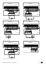
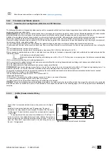
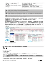
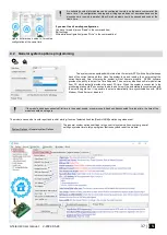
Figure 26 2-wire smoke detector wiring diagram
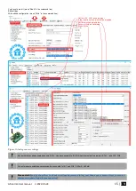
1.
Connect the [2-wire] smoke detector (current sensor) to the
I/O1, I/O2 inputs as in the wiring diagram.
2.
Connect the power supply.
3.
Install SERA2 software.
4.
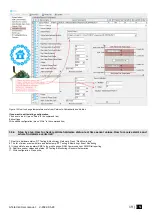
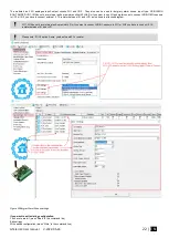
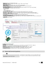
Go to “System Options> General System Options” from the
menu and select 2-Wire Smoke Detector (Fire current loop)
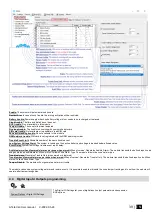
5.
In the Zone table set I/O1 definition to “Fire”

