background image

13(16)

2.6  Connecting Wireless Devices

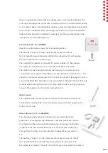
Switch between normal mode and installation mode:

Press and hold ON and DELAYED OFF simultaneously for 3 seconds to switch modes. 
A short beep indicates the shift. 


The ALARM LED is constantly lit when the unit is in the installation mode.


Press DELAYED OFF to see how many wireless devices are installed. The number of 
flashes corresponds to the number of wireless devices. A long beep indicates that no 
wireless devices are installed.
Press and hold ON and DELAYED OFF simultaneously for 3 seconds to switch back to 
normal mode.

Installing the remote unit and water detector:

Switch to installation mode as above.
Put the remote unit / water detector in installation mode by restarting it. (Remove 
the batteries, wait 1 minute, plug in the batteries, the unit beeps, the installation 
mode automatically switches to normal mode after 5 minutes)
When the control unit receives the installation signal, ON flashes green.
Press ON to install the device. A short beep and a ON flashing green indicate that 
the unit has been added. 
If OFF instead flashes red, no more units can be installed. A maximum of 16 wireless 
units can be installed.


Press DELAYED OFF to see how many wireless devices are installed. The number of 
flashes corresponds to the number of wireless devices. A long beep indicates that no 
wireless devices are installed.

Uninstalling the remote unit and water detector:

Switch to installation mode as above.
Individual devices cannot be deleted. All devices are deleted at the same time. 
Afterwards you need to put all the remaining units back as above.
Press and hold OFF for three seconds. All units are deleted, and the deletion is 
confirmed with a long beep and OFF flashing red.


Summary of Contents for WaterFuse Apartment

Page 1: ...1 16 WaterFuse Apartment User Manual Installation Instructions...

Page 2: ...duct may only be connected by a qualified installer The warranty does not cover repairs of faults caused by faulty installation or incorrect use of the appliance The ball valves have been tested by Si...

Page 3: ...1 4 Alarm 7 1 5 Faults 7 1 6 External Control 7 2 Installation Instructions 8 2 1 General 8 2 2 Installation 8 2 3 Settings 10 2 4 Connection to Alarm 11 or Other Remote Controls 2 5 Connecting the Ca...

Page 4: ...water distribution cabinet and wireless water detectors can be placed under the dishwasher or sink The water detectors function as a smoke alarm but with water If they indicate water a signal is sent...

Page 5: ...ndicator next to the knob shows open closed Fitted in the water distribution cabinet Water sensor The water sensor is placed in the water distribution cabinet and when water is indicated the control u...

Page 6: ...touch water in case of a leak resulting in rising water level for example in the threshold 1 3 Daily Operation Monitoring of the water system takes place continuously and no daily measures need to be...

Page 7: ...ng normal use the batteries have a life expectancy of at least 2 years Radio communication errors If the radio communication between different devices stops working or does not work satisfactorily thi...

Page 8: ...mote devices and water detectors A washing machine can be placed in the kitchen without a floor drain if there is a waterproof surface and a water detector connected to a water switch by wire or wirel...

Page 9: ...the 6 pole terminal K80 on V1 and V2 with the red cable to The cable from the water sensor goes to the central unit where it is plugged in to Prb on terminal block K81 All cables can be connected at...

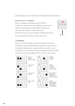
Page 10: ...s screwed to the wall Check that there are no electrical cables or installations within 50 cm of the device as this impairs the radio transmission 2 3 Settings There are a number of settings that can...

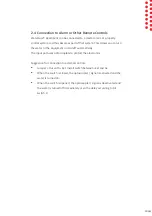
Page 11: ...t on and off automatically The input port uses optocouplers to protect the electronics Suggestion for connection to external controls Jumper Out with Ext Install switch between Ext and 0v When the swi...

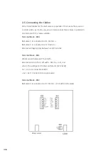
Page 12: ...nal block K80 Ball valve 1 is connected to V1 Red on Ball valve 2 is connected to V2 Red on External voltage supply between 12 24 and 0v Terminal block K81 Water sensor between Prb and Prb External co...

Page 13: ...te plug in the batteries the unit beeps the installation mode automatically switches to normal mode after 5 minutes When the control unit receives the installation signal ON flashes green Press ON to...

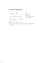
Page 14: ...15 G20 DN15 DN20 2 AA 1 5v batteries for remote unit Motorised ball valves with manual override 2 AA 1 5v batteries for water detector Battery life is expected to exceed 2 years Radio transmission up...

Page 15: ...cable This means that shipping costs inspection and assem bly costs are not included in the warranty commitment If possible use the original packaging if the product needs to be transported The transp...

Page 16: ...16 16 Tel 018 349010 info tollco se www tollco se Tollco AB Rubanksgatan 4 741 71 Knivsta...

Reviews: