8
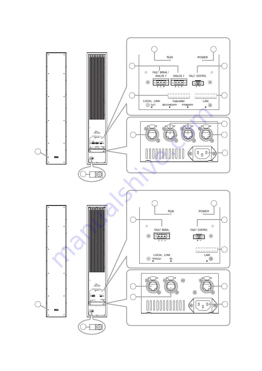
7. NOMeNcLATUre AND FUNcTIONS
• SR-D8-M
[Rear]
[Rear Terminals]
[Bottom Terminals]
[Front]
15
1
2
3
4
5
6
7
9
10
11
12
1314
• SR-D8-S
Page 1: ...r SR D8CS Wall mounting adapter SR D8CL Extension plate SR D8EP Wall mounting bracket SR D8WB Hoisting bracket SR D8HB Fixing bar SR D8FB Thank you for purchasing TOA s Active Line Array Speaker Syste...
Page 2: ...ration 14 10 3 Connection Example 3 Analog Line Connection 15 10 4 Connection Example 4 Maximum System 16 10 5 Removable Terminal Plug Connection 18 10 6 Fixing Power Supply Cord 19 10 7 System Expans...
Page 3: ...g prong The wide blade or the third prong are provided for your safety If the provided plug does not fit into your outlet consult an electrician for replacement of the obsolete outlet Protect the powe...
Page 4: ...rsonal injury and or property damage Do not use this speaker in a flying installation Never use the eyebolt mounted on top of the speaker stack multi unit line array for the purpose of permanent insta...
Page 5: ...nor remove the power supply plug with wet hands as doing so may cause electric shock When unplugging the power supply cord be sure to grasp the power supply plug never pull on the cord itself Operatin...
Page 6: ...requency woofers 24 small high frequency tweeters and an 8 channel 30 W 4 output digital power amplifier Close vertical arrangement of the sound source speaker units creates a continuously linear soun...
Page 7: ...temperature is between 0 and 40 C 32 and 104 F and the moisture is less than 90 no dew condensation must be formed The units are precision audio components To prevent failure avoid locations where the...
Page 8: ...8 7 Nomenclature AND FUNCTIONS SR D8 M Rear Rear Terminals Bottom Terminals Front Front Rear Rear Terminals Bottom Terminals 15 15 1 1 2 3 4 5 2 3 5 6 7 7 8 9 10 11 10 11 12 13 14 SR D8 S...
Page 9: ...er apply any voltage to it Up to 4 units terminals can be connected in parallel 6 MAC address CobraNet MAC address for CobraNet 7 MAC address CONTROL MAC address for the LAN 8 Local link output termin...
Page 10: ...inals can be connected in parallel 13 Local link through terminal LOCAL LINK THROUGH Outputs signals from SR D8 M to SR D8 S s Local link input terminal 14 when interconnecting SR D8 M and SR D8 S uni...
Page 11: ...Hex bolt M6 20 with spring and plain washers paint 8 Hex bolt M10 30 with spring and plain washers paint 4 Wall bracket Speaker bracket SR D8HB Hoisting Bracket SR D8FB Fixing Bar Hoisting bracket Ey...
Page 12: ...itted with RJ45 connectors for connection Up to 4 stacks up to 16 speakers can be controlled by a single PC Note Do not connect the LAN terminal directly to the PC PC with the SR D8 PC Software instal...
Page 13: ...4 dB model D 2000AD1 E H C 4 3 2 1 1R 2R 1L 2L 3L 3R 4L 4R model D 936R STEREO SELECT INPUT MODULE 10 dB 4 3 2 1 LINE OUTPUT MODULE 10 4 dB model D 2000DA1 1 2 3 E H C Microphone BGM player Cassette...
Page 14: ...E OUTPUT MODULE 10 4 dB model D 2000DA1 1 2 3 E H C Microphone BGM player Cassette deck CD player MD player etc PC Digital mixer D 2008SP D 2000AD1 D 936R D 2000DA1 Rear terminals Switch SR D8 M SR D8...
Page 15: ...dB model D 2000AD1 E H C 4 3 2 1 1R 2R 1L 2L 3L 3R 4L 4R model D 936R STEREO SELECT INPUT MODULE 10 dB 4 3 2 1 LINE OUTPUT MODULE 10 4 dB model D 2000DA1 1 2 3 E H C Microphone BGM player Cassette dec...
Page 16: ...1 2 3 E H C Microphone BGM player Cassette deck CD player MD player etc PC Digital mixer D 2008SP D 2000AD1 D 936R D 2000DA1 Switching hub for CobraNet Switching hub 1 for LAN To switching hub 2 Rear...
Page 17: ...D8 M SR D8 S SR D8 S SR D8 S To switching hub 1 B 1 B 2 B 3 B 3 B 3 B 3 SR D8 M SR D8 S SR D8 S SR D8 S C 1 C 2 C 3 C 3 C 3 C 3 SR D8 M SR D8 S SR D8 S SR D8 S D 1 D 2 D 3 D 3 D 3 D 3 To B 3 To C 3 T...
Page 18: ...ule terminal 2 x 0 5 mm2 AWG 20 cable No 4 ferrule terminal Cable sheath to trim Insulation sleeve Contact section Insulation sleeve Contact section a l2 a 1 a2 l1 l2 l1 b b Solid cable and stranded c...
Page 19: ...vent the power supply cord from being accidentally pulled out fix it using the supplied cord clamp as shown at right SR D8 M rear SR D8 S rear Power cord supplied with the SR D8 S Cord clamp Power cor...
Page 20: ...etween each of the SR D8 M and the switching hub is less than 100 m 110 yd Be sure to make connections of both terminals PRIMARY and SECONDARY Audio signals may be interrupted temporarily at the time...
Page 21: ...er of hubs cascade connected from the SR D8 M should be 3 or less A method of connecting a single unit s CobraNet PRIMARY and SECONDARY terminals to each different switching hub to prevent the system...
Page 22: ...tion completion Perform spanning tree setting within switching hubs For the settings refer to the instruction manual of the switching hub Audio signals may be interrupted temporarily at the time when...
Page 23: ...nd SECONDARY terminals of each unit are connected to the same switching hub Notes Cycle the entire system s power after connection completion Contact your TOA dealer for more information on switching...
Page 24: ...er Remark SR D8WB Wall Mounting Bracket 2 Arrange 9 sets of M10 anchor bolts and M10 nuts separately SR D8CS Wall Mounting Adapter 1 SR D8FB Fixing Bar 2 Use when setting left or right angles to over...
Page 25: ...ngles can be adjusted within a range of 0 90 If no angle adjustments are required this completes the installation When performing angle adjustments please refer to Angle Adjustment on p 31 Unit mm in...
Page 26: ...ll the unit on the wall tilting over 30 Never adjust the speaker angle to the left or right when the unit is installed facing up or down WARNING 11 2 1 Required mounting brackets 2 Unit Configuration...
Page 27: ...all bracket of the SR D8WB SR D8CL Hex bolt M8 25 with spring and plain washers supplied with the SR D8CL 2 Hex bolt M8 25 with spring and plain washers supplied with the SR D8CL 2 32 125 418 16 46 35...
Page 28: ...both sides of the lower part of each speaker bracket SR D8 S 5 6 4 Hex bolt M6 20 with spring and plain washers 1 Hex bolt M10 30 with spring and plain washers 3 Speaker bracket of the SR D8WB Hoistin...
Page 29: ...etes the installation When performing angle adjustments please refer to Angle Adjustment on p 31 7 7 8 Enlarged figure of previous page Part A 3 Supplied with the SR D8WB Hex bolt M10 30 with spring a...
Page 30: ...2 2 2046 4 80 57 125 353 13 9 125 418 16 46 418 16 46 353 13 9 353 13 9 418 16 46 353 13 9 418 16 46 32 125 1 26 4 92 1 26 4 92 4 92 4 92 4 92 4 92 4 92 120 4 4 74 14 12 28 14 0 47 1 1 19 0 47 1 1 32...
Page 31: ...et Step 3 Securely tighten the loosened bolts Note The removed bolts in Step 1 are not used 1 5 1 5 x 6 9 0 Speaker bracket upper side When directing to the right facing the speaker front Loosen Remov...
Page 32: ...the removed bolts in Step 1 and a nut supplied with the SR D8FB Step 4 Direct the speaker unit to your desired angle Step 5 Securely tighten all loosened bolts and nuts Note The removed bolts except...
Page 33: ...ay Speaker Systems Unit mm in 12 2 Brackets 12 2 1 SR D8CL Wall Mounting Adapter Unit mm in 12 2 2 SR D8CS Wall Mounting Adapter Unit mm in 50 1 97 642 2 25 28 33 1 3 Top Side Front Rear SR D8 M Rear...
Page 34: ...12 2 6 SR D8FB Fixing Bar Unit mm in L bracket R bracket Wall bracket Speaker bracket Hoisting bracket Eyebolt 15 2 0 6 194 2 7 65 275 10 83 15 2 0 6 194 2 7 65 275 10 83 254 10 120 4 4 74 52 2 05 16...
Page 35: ...ia the specified switching hub Max extend distance 100 m 109 36 yd connected via a switching hub Note This network should be completely independent of other LAN Control LAN TCP IP 100BASE TX 1 system...
Page 36: ...cause harmful interference to radio communications Operation of this equipment in a residential area is likely to cause harmful interference in which case the user will be required to correct the inte...