11
7. CONNECTIONS
7.1. Notes on Connections
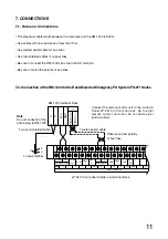
• The maximum cable length between the main rack and the RM-1200 is 800 m.
• Use cables with line resistance of less than 10
Ω
.
• Use twisted paired cable for bus lines.
• Use twin shielded cables for signal lines.
• Be sure to connect the RM-1200's bus line to BUS 1 terminal.
• Be sure to match the polarity of bus lines.
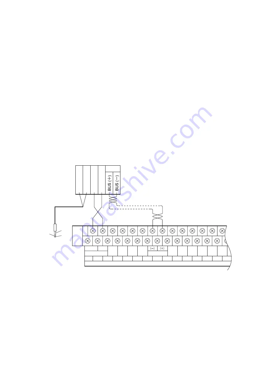
7.2. Connection of the RM-1200 to the Rack-Mounted Emergency PA System FS-971 Series
Connect the remote control unit to the Junction
Panel JP-0410 in the main rack. Up to eight
remote control units can be connected per
junction panel.
H
C
24V
GND
1
E
H
C
JP-0410 front panel middle row terminal block
GND
GND
GND
GND
GND
GND
24 V
CHIME
ACTI
GEM RM PWR
1
1
2
2
3
4
5
6
7
8
1
9
10
11
12
IN USE
REMOTE REMOTE
TIMER
GEN RM BUS
PWR FAIL
CTRL
AUX CONTROL
To pre-amplifier
RM-1200 terminal block
Note
Do not connect E of the
phone plug to RM-1200.
Two-core shielded cable
Twisted paired cable
Observe correct polarity
of bus lines.
Summary of Contents for RM-1200
Page 19: ......


