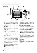
12
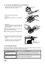
7.3. Connection of the RM-1200's Push-in Terminal Block
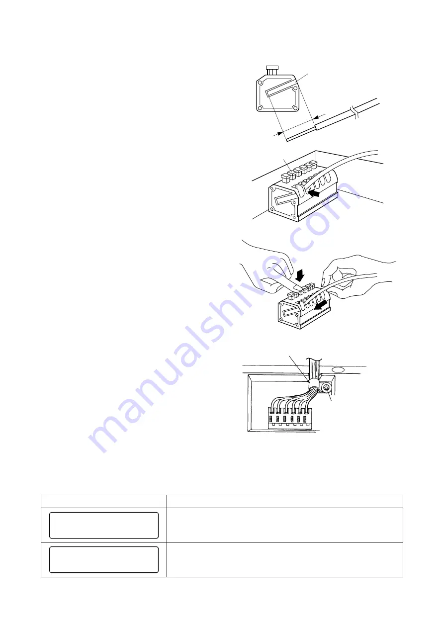
1. Strip the cable sheath 9 mm using the strip gauge
provided on the side of the terminal block.
2. Insert the cable into the terminal block.
• Solid cable
Fully Insert the cable into the hole in the terminal
block.
• Twisted cable
Press the lock switch on the terminal block, and
fully insert the cable. Then, release the switch with
the cable inserted.
When removing the cable, pull it out of the terminal
block while pressing the lock switch.
Note :
Do not press the lock switch extremely strong.
3. After connection completion, bundle cables
together using the cable clip, then fix the clip with
a screw.
If cables are too thick to be bundled together,
replace the cable clip with the supplied clip.
7.4. Error Message Indication
When error messages are displayed on the screen after connection and setting completion, the following
causes can be considered. Check the connections and settings again.
9 mm
Strip gauge
Lock switch
Cable clip
Note
Do not tighten the clip
extremely strong.
P o l
i n g
E r r o r
l
RM -
U S
E r r o r
B
Error Message Indication
1. Bus line disconnection between the main rack and RM-1200
2. Reversed bus line polarity between the main rack and RM-1200
3. Connected RM-1200 numbers are set for "0" at the main rack.
1. Wrong address setting at the RM-1200
2. Wrong setting of connected RM-1200 numbers at the main rack.
Possible Cause
Summary of Contents for RM-1200
Page 19: ......


