


TM 9-1829A, April 1944
71/100
2021-07-07
b.
Operation
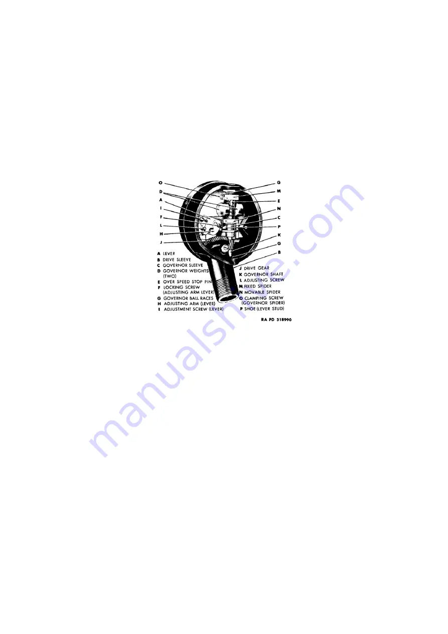
(fig. 105): The flexible shaft turns the drive shaft housed in drive sleeve (B). On the end of drive
shaft is a helical drive gear (J), made of fiber. This drive gear meshes with the pinion on the governor shaft
(K). On the governor shaft are two weights (D) diametrically opposite each other. Each weight is connected
with each link by a pin which allows the parts to hinge. One end of the link is pivoted freely to a fixed spider
(M) on the governor shaft; the other link end is pivoted freely to a sleeve (C) which slides readily over the
governor shaft. Trapped in between the fixed spider and sleeve on governor shaft is a spring which balances
the centrifugal force at a given speed, and acts as a restoring force when speed is reduced. Placed on the upper
spider is an overspeed stop pin (E) which prevents the governor spring from setting coil upon coil. As the
governor shaft (K) revolves, the two weights (D) are thrown outward, due to centrifugal force, raising the
sliding sleeve (C), the shoulder of which engages a flat shoe (P), pivotally mounted on lever (A) which,
through a suitable gear train, pivoted on the same center as the lever, engages a pinion (not shown) on the
pointer shaft, moving the pointer and indicating the revolutions per minute. The pointer shaft has a bronze
hair spring for returning the pointer to zero and providing a means of removing any lost motion in this train
of parts.
Figure 105: Centrifugal tachometer mechanism installed
37. Bench test procedure
a.
Test for tight mechanism:
This is done by using a short piece of inner core (3 to 4 inches long) with proper
tip to fit the drive position at neck of instrument being tested (fig. 14). If tightness or binding is apparent it is
caused by lack of lubrication in governor shaft or drive shaft bearings, dirty mechanism, or stripped drive
gear. Instrument must be disassembled and repaired before further tests can be made.
b.
Test calibration:
Providing instrument is not “bound up” (test a, above) place it on the calibrating machine
(T-170645) and run at various speeds. Note instrument readings obtained as compared with master head. The
causes and remedies of any irregularities can be found by referring to subparagraph e following.
c.
Probable causes and remedies of defective tachometers:
(1)
Pointer fluctuates or wavers:
a)
Stripped drive gear: Replace with new part.
b)
Dirty or worn governor assembly or pointer mechanism: Clean or replace.
(2)
Sticky pointer
(pointer does not return to zero).
a)
Weak or broken hair Spring: Replace pointer mechanism (includes hair spring).
b)
Worn or dirty gears in pointer mechanism: Clean or replace.
c)
Defective maximum hand: Indicating pointer may catch on maximum hand, which can be corrected
by bending.
(3)
Pointer remains at zero:
a)
Stripped drive gear: Replace.
b)
Defective or dirty governor assembly or pointer mechanism: Clean or replace.
c)
Defective maximum hand: Ratchet at back of face dial may be so tight that indicating pointer cannot
push maximum hand forward. Correct by bending ratchet spring.
d)
Excessive noise: Due to principles of operation, centrifugal type tachometers are necessarily noisier
in operation than magnetic type instruments. Therefore, a whirring noise in the instrument when
operated at high speed does not necessarily indicate trouble.