


TM 9-1829A, April 1944
19/100
2021-07-07
(1)
Pinion and carrier:
Place pinion in slot of carrier and revolve pinion. Discard pinion if slightest binding
is apparent. Examine gear teeth of pinion and discard pinion if teeth are marred. Replace pinion carrier
if burs or other sources of binding are apparent from touch or sight.
(2)
Magnet shaft collar:
Replace if damaged.
(3)
Speed cup:
Slight roughness at bearing points of the spindle can sometimes be cleaned with crocus cloth.
Speed cups must be in static balance and concentric to operate properly. Clearance between magnet and
speed cup, and speed cup and field plate are close. Accordingly, it is recommended that the speed cup be
replaced if at all questionable. Adequate hair spring action can only be obtained when the spring is
horizontal, and each coil is evenly spaced when checked in the wound position. To obtain this condition
the hair spring must be trued with tweezers to give clearance between coils when spring is in wound
position.
(4)
Main frame:
Magnet shaft bearing surface must be mirror bright, and free from scratches. Install magnet
shaft into main frame and replace frame if more than 0.003 inch to 0.004 inch side play is apparent.
(5)
Odometer shaft:
Roll on surface plate to insure being perfectly straight. Shaft should check 0.125 inch
di0.000 inch to 0.0005 inch. Discard if worn or bent.
(6)
All gears:
Replace gears if burred, nicked, or worn at teeth.
(7)
Figure wheels:
Replace if numerals are marred or inner ring teeth are damaged.
(8)
Magnet and shaft:
Replace magnet if it will not take a magnetic charge. Replace “N” series magnets if
the flaring end is too short to form an adequate flare over the retaining collar. Replace magnet if the
speed cup staff bearing is rough, or if the bearing causes the speed cup to drag. Note: See calibration
(par. 9) for more information.
(9)
Dial:
Visually inspect for general appearance, flatness, paint mars, chipped luminous numerals and
graduations. Depending on available facilities, a damaged dial may be repaired or replaced.
8. Assembly
a.
Install magnet and shaft:
These assembly instructions are based on the assumption that the speedometer
main frame is positioned in the same manner as when installed in the vehicle. Place front thrust washer on
magnet shaft, lubricate first gear teeth with No. 00 grease, O.D.; oil magnet shaft bearing lightly with watch
and clock oil; insert first gear into position in frame and place thrust washer around rear end.
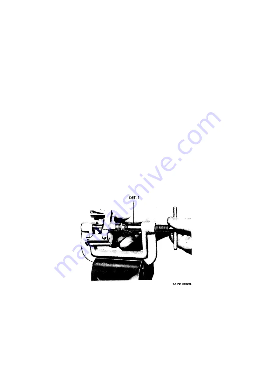
Figure 21: Pressing collar on magnet shaft, using fixture (T-170666 with Det. 1)
(1)
“L” series speedometer:
Place retaining collar over square end of magnet shaft with small shoulder to
rear and press into place with clamp (T-170666 with Det. 1).
(2)
“N” series speedometer:
Seat the retaining collar with groove to rear on lower end of magnet shaft with
tool (T-170666 with Det. 1). Retaining collar is seated when first gear end play is barely perceptible.
Stake the protruding magnet shaft stock over the collar with tool (T-170666 with Det. 6).
(3)
Allowable end play for both “L” & “N” series:
After the foregoing operations, it is important that
magnet shaft turn freely; in addition, its end play must be barely perceptible (approx. 0.001 inch to
0.003 inch) when moved with the fingers. If magnet shaft does not turn freely, this can usually be
corrected on the model “L” by tapping the squared end of shaft lightly with a small rawhide hammer.
Correction on model “N” requires use of tool (T-170654, fig. 20).