


TM 9-1829A, April 1944
68/100
2021-07-07
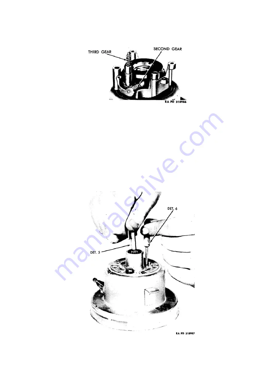
Lubricate gear teeth of third gear with small amount of No. 00 grease, O.D., and place in position in main
frame (fig. 101). Make sure that small friction washer is on upper end of third gear shaft and fasten odometer
assembly to frame with three screws (fig. 99). Test for binds in odometer gearing.
Figure 101: Mechanism with speed unit and odometer frame removed to show position of second and third gears
h.
Replace case:
Place mechanism in case-and fasten with two screws and lock washers. If instrument has elbow
joint, place small amount of No. 00 grease, O.D., on gear teeth, screw bevel gear and sleeve assembly into
elbow (fig. 80) and fasten assembly to back of instrument (fig. 79). If too much play is found in the gears
after assembly, remove the bevel gear and sleeve (fig. 80) and lightly dress down the face of the brass sleeve
(with a file) until a closer meshing of gear teeth is obtained.
i.
Calibrate:
Hold dial in position, and press pointer lightly on staff at zero. Place unit on calibrating machine,
hold in same position as it will be on vehicle, run master head on machine at 10 miles per hour and make any
necessary corrections in instrument by adjusting hair spring collet on staff (fig. 72). If instrument is
excessively fast it may be necessary to install a stronger hair spring or shorten the hair spring. Cutting off one
coil will slow up instrument about 6 miles per hour. Not more than three coils should be removed. Allow
pointer to return to zero to check whether it returns easily. Run master at 30 and 60 miles per hour. If
instrument is too slow at high speeds either a weaker hair spring must be installed (par. 35 e), or the magnet
strengthened with the magnet regulator (fig. 102).
Figure 102: Moving magnet regulator, using adjusting kit (T-178715)