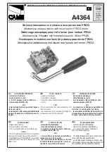
background image

Anvil adjustment:

After adjustments to the stroke, it is necessary to adjust the anvil (5) and 
its counter lock nut (6). Open the levers up to maximum, there is a clicking 
sound, to extend the mandrel completely. The protrusion of the mandrel out 
of the anvil must be as long as the whole rivet nut. Unscrewing the counter 
lock nut (6) to adjust the anvil (5) by turning left or right, to increase or 
decrease the length. After the correct length is applied, screw the counter 
lock nut until it is tight. Changing the threaded inserts or stroke requires this 
step every time. 

Setting a threaded insert:

Put the tool in start position by opening the levers up to maximum. There 
is a clicking sound. The mandrel will extend completely and the ratchet 
mechanism is unlocked. Screw the insert on the threaded end of the 
mandrel and insert it into the hole of the material. The hole size must 
be slightly larger the rivet nut, check the drill specifications of the rivet 
nut. Close the levers completely once to activate the ratchet mechanism. 
Now open de levers for one third till you hear the clicking sound of the 
mechanism, then close the levers completely. Repeat these steps to clamp 
the rivet nut into the material tightly. After the rivet nut is set, unscrew the 
threaded insert, by using the turning knob on the mandrel. 

Important:

 after having started setting the rivet nut, do not open the levers 

completely anymore before the rivet nut has been set. When levers have 
been opened completely before having set the rivet nut, the ratchet process 
has to be started again. 

D

C

6

Manual


TIOS HN12 PT      |   

3

Handbuch


TIOS HN12 PT      |   

7

8

9

10

11

12

13

14

15

17

18

16

19

20

21

22

23

24

25

26

1

3

5

6

4

2

31

32

30

33

38

41

42

43

44

45

34

35

36

37

39

40

27

29

28

TIOS HN12 PT

the marked items are consumables (not covered by any guarantee)

1

04P00950

13

04P00715

25

04P00726

37

04P00960

2

04A00230

14

04P00716

26

04P00727

38

04P00969

3

04P00958

15

04P00721

27

04P00972

39

04P00970

4

04P00704

16

04P00717

28

04P00541

40

04P00971

5

04P00807

17

04A00218

29

04F00103

41

04A00236

6

04P00806

18

04P00713

30

04P00904

42

04A00235

7

04A00231

19

04A00219

31

04F00100

43

04A00234

8

04P00706

20

04P00816

32

04P00720

44

04A00233

9

04P00705

21

04P00722

33

04P00968

45

04A00232

10

04P00707

22

04P00723

34

04P00966

47

04P00625

11

04A00217

23

04P00724

35

04P00964

48

04P00626

12

04P00714

24

04P00725

36

04P00962

6

5


click

unlock

Summary of Contents for TIOS HN12 PT

Page 1: ...ne andere Abmessung Wechsel zu einer anderen Abmessung Lösen Sie die Kontermutter 6 und drehen Sie das Mundstück 5 heraus Drücken Sie leicht auf den Gewindedorn und ziehen dann den Pin zur Sicherung des Gewindedornes heraus Wählen Sie den benötigten Umrüstsatz und montieren Sie in umgekehrter Reihenfolge den Gewindedorn und das Mundstück Hubeinstellung Schließen Sie die Hebel 2 vollständig die Bac...

Page 2: ...ebel ganz Dieser Schritt ist entsprechend der Hubzahl zu wiederholen Anschließend den Gewindedorn mittels des Drehknopfes 3 herausdrehen Prüfen Sie den festen Sitz der Blindnietmutter Wichtig Nach dem Einstellen der Nietmutter dürfen die Hebel nicht komplett bis zum Anschlag geöffnet werden da ansonsten die Ratschenmechanik ausgeschaltet ist In diesem Fall wie oben beschrieben vorgehen D C 2 Handb...

Page 3: ...f the mechanism then close the levers completely Repeat these steps to clamp the rivet nut into the material tightly After the rivet nut is set unscrew the threaded insert by using the turning knob on the mandrel Important after having started setting the rivet nut do not open the levers completely anymore before the rivet nut has been set When levers have been opened completely before having set ...

Page 4: ...5 and the lock nut 6 Push slightly on the mandrel to release the spring and take out the mandrel pin The mandrel can now be changed Replace it by choosing the correct size from the spare parts in the carton box Stroke adjustment Close the left and right lever 2 completely in this way the jaws and internal spring are released Loosen the adjust nut 8 and turn the front sleeve 7 with stroke indicator...

Page 5: ...5 and the lock nut 6 Push slightly on the mandrel to release the spring and take out the mandrel pin The mandrel can now be changed Replace it by choosing the correct size from the spare parts in the carton box Stroke adjustment Close the left and right lever 2 completely in this way the jaws and internal spring are released Loosen the adjust nut 8 and turn the front sleeve 7 with stroke indicator...

Page 6: ...f the mechanism then close the levers completely Repeat these steps to clamp the rivet nut into the material tightly After the rivet nut is set unscrew the threaded insert by using the turning knob on the mandrel Important after having started setting the rivet nut do not open the levers completely anymore before the rivet nut has been set When levers have been opened completely before having set ...

Page 7: ...ebel ganz Dieser Schritt ist entsprechend der Hubzahl zu wiederholen Anschließend den Gewindedorn mittels des Drehknopfes 3 herausdrehen Prüfen Sie den festen Sitz der Blindnietmutter Wichtig Nach dem Einstellen der Nietmutter dürfen die Hebel nicht komplett bis zum Anschlag geöffnet werden da ansonsten die Ratschenmechanik ausgeschaltet ist In diesem Fall wie oben beschrieben vorgehen D C 2 Handb...

Page 8: ...ne andere Abmessung Wechsel zu einer anderen Abmessung Lösen Sie die Kontermutter 6 und drehen Sie das Mundstück 5 heraus Drücken Sie leicht auf den Gewindedorn und ziehen dann den Pin zur Sicherung des Gewindedornes heraus Wählen Sie den benötigten Umrüstsatz und montieren Sie in umgekehrter Reihenfolge den Gewindedorn und das Mundstück Hubeinstellung Schließen Sie die Hebel 2 vollständig die Bac...

Reviews: