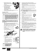
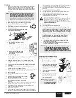
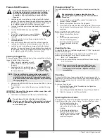
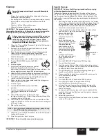
background image

English

English

© Titan Tool Inc.  All rights reserved. 

9

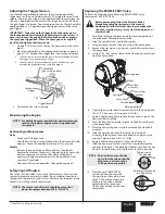
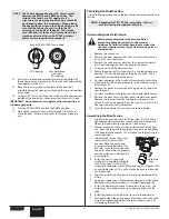
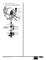
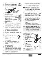
cleanup

Special cleanup instructions for use with flammable 

solvents:


•  Always flush spray gun preferably outside and at least one 

hose length from spray pump.


•  If collecting flushed solvents in a one gallon metal container, 

place it into an empty five gallon container, then flush 

solvents.


•  Area must be free of flammable vapors.


•  Follow all cleanup instructions.

ImPORTANT:  The sprayer, hose, and gun should be cleaned 

thoroughly after daily use.  Failure to do so permits material to 

build up, seriously affecting the performance of the unit.

Always spray at minimum pressure with the gun spray 

tip removed when using mineral spirits or any other 

solvent to clean the sprayer, hose, or gun.  Static 

electricity buildup may result in a fire or explosion in 

the presence of flammable vapors.

  1.  Follow the “Pressure Relief Procedure” found in the Operation 

section of this manual.

  2.  Remove the gun tip and tip guard and clean with a brush 

using the appropriate solvent.

  3.  Place the siphon tube into a container of the appropriate 

solvent (refer to recommendations of the material 

manufacturer).  An example of the appropriate solvent is 

water for latex paint.

  4.  Place the return hose into a metal waste container.

SPRAY

PRIM

E

  5.  Turn the PRIME/SPRAY knob to the PRIME 

position.

  6.  Start the engine.
  7.  Slowly turn the DirectLink pressure control 

knob counterclockwise to increase the 

pressure until fluid starts to come out of the return hose.  Use 

only enough pressure to keep the fluid coming out.

  8.  Allow the fluid to circulate through the sprayer and flush the 

paint out of the return hose into the metal waste container.

  9.  Turn off the sprayer by pressing and holding the engine 

shutoff switch until the motor shuts off.

  10.  Place a metal waste container underneath the spray gun to 

catch the paint and solvent.

  11.  Start the engine.

SPRAY

PRIME

  12.  Turn the PRIME/SPRAY knob to the SPRAY 

position.

  13.  Turn the DirectLink pressure control knob 

slowly counterclockwise to increase the 

pressure.  

  14.  Fully pull the spray lever on the cart handle 

to trigger the spray gun.  Fluid will begin flowing through the 

spray hose and out of the gun.

  15.  Continue to pull the spray lever on the cart handle until the 

material is flushed out of the hose and the solvent coming out 

of the gun is clean.

  16.  Release the spray lever.

  NOTE:  For long-term or cold weather storage, pump Pump 

Saver™ through the entire system.

  17.  Follow the “Pressure Relief Procedure” found in the Operation 

section of this manual.

  18.  Store the sprayer in a clean, dry area.
ImPORTANT:  Do not store the sprayer under pressure.

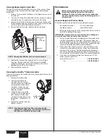
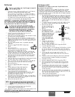
Special cleanup

ImPORTANT:  Perform the following procedure after spraying 

with water-based materials only.
Perform the following procedure when the valves of the sprayer 

are stuck or when preparing the sprayer for long term storage.  The 

use of a pump cleaning adapter that attaches to the bottom of the 

siphon tube is required (the pump cleaning adapter is included with 

the sprayer).
  1.  Lock the gun and remove the spray tip assembly.  If necessary, 

loosen the gun holder clamp knob and then engage the spray 

gun trigger lock.  Move the spray gun to its original position 

and tighten the clamp knob.  Place the suction tube and 

return tube into an empty waste container.

  2.  Using a garden hose, rinse off the siphon tube, return hose 

and inlet filter.  Empty the waste container.

Seals

Garden

hose

Pump

cleaning

adapter

Siphon

tube

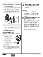
  3.  Remove the inlet filter 

from the suction tube 

and place into a waste 

container.

  4.  Verify that the seals are 

present inside the adapter 

and suction tube. Thread 

the pump cleaning 

adapter onto a garden 

hose.  Connect the hose 

and adapter to the fitting 

on the end of the siphon 

tube.

  5.  Unclip the return hose 

from the siphon tube and 

place it into the waste 

container.

  6.  Turn the PRIME/SPRAY knob to the PRIME position.
  7.  Turn on the water supply.
  8.  Start the engine.  Water will go into the siphon tube and out 

through the return hose.  Let the sprayer run for a few minutes 

to allow the return hose to be flushed.

  9.  Turn off the sprayer by pressing and holding the engine 

shutoff switch until the motor shuts off.

  10.  Place a metal waste container underneath the spray gun to 

catch the cleaning solution.

  11.  Start the engine.
  12.  Turn the PRIME/SPRAY knob to the SPRAY position.
  13.  Turn the DirectLink pressure control knob slowly 

counterclockwise to increase the pressure.  

  14.  Fully pull the spray lever on the cart handle to trigger the 

spray gun.  Fluid will begin flowing through the spray hose 

and out of the gun.

  15.  Continue to pull the spray lever on the cart handle until the 

material is flushed out of the hose and the water coming out 

of the gun is clean.

  16.  Release the spray lever.
  17.  Follow the “Pressure Relief Procedure” found in the Operation 

section of this manual.

Summary of Contents for 0290005

Page 1: ...nings and instructions Please read and retain for reference SPEEFLO PowrLiner 850 Owner s Manual Notice d utilisation Manual del Propietario Do not use this equipment before reading this manual Register your product online at www titantool com Serial Number _ _ _ _ _ _ _ _ _ _ Model Number 0290005 ...

Page 2: ... when cleaning and changing nozzle tips In the case where the nozzle tip clogs while spraying ALWAYS lock gun trigger shut pump off and release all pressure before servicing cleaning tip or guard or changing tip Pressure will not be released by turning off the motor The PRIME SPRAY valve or pressure bleed valve must be turned to their appropriate positions to relieve system pressure Refer to PRESS...

Page 3: ... understand the operation of all controls Never permit anyone to operate the engine without proper instructions 5 Gasoline is extremely flammable and is explosive under certain conditions 6 Refuel in a well ventilated area with the engine stopped Do not smoke or allow flames or sparks in the refueling area or where gasoline is stored 7 Do not overfill the fuel tank After refueling make sure the ta...

Page 4: ... engine speed under normal load change brands of gasoline If spark knock or pinging persists consult an authorized dealer of the engine manufacturer Failure to do so is considered misuse and damage caused by misuse is not covered by the engine manufacturer s limited warranty Occasionally you may experience light spark knock while operating under heavy loads This is no cause for concern it simply m...

Page 5: ...t of this manual before operating this equipment 1 Attach the handle to the cart Handle adjustment knob Handle knob a Line up the hole in the bottom of the handle with the support weldment on the cart b Thread the bolt through the hole in the handle and the weldment Tighten by turning the knob of the bolt clockwise c Position the handle at the desired height Loosen the knob on the rear of the supp...

Page 6: ...ntil the engine starts d Once the engine is running slowly move the choke lever down to the closed position NOTE If you are having trouble starting the motor rotate the DirectLink pressure control knob 1 2 turns counter clockwise 7 Slowly turn the DirectLink pressure control knob counterclockwise to increase the pressure until fluid starts to come out of the return hose Use only enough pressure to...

Page 7: ...ease the spray lever 20 Lock the gun by turning the gun trigger lock to the locked position If necessary loosen the gun holder clamp knob and then engage the spray gun trigger lock Move the spray gun to its original position and tighten the clamp knob 21 Turn the DirectLink pressure control knob fully clockwise to minimum 22 Turn the PRIME SPRAY knob to PRIME 23 Turn off the sprayer by pressing an...

Page 8: ... attempt to clean the tip with your finger Do not use a needle or other sharp pointed instrument to clean the tip The hard tungsten carbide is brittle and can be chipped Changing a Spray Tip Tips can be removed and replaced easily without disassembling the gun Never attempt to change or clean the tip or tip guard without first performing the Pressure Relief Procedure 1 Perform the Pressure Relief ...

Page 9: ... gun is clean 16 Release the spray lever NOTE For long term or cold weather storage pump Pump Saver through the entire system 17 Follow the Pressure Relief Procedure found in the Operation section of this manual 18 Store the sprayer in a clean dry area IMPORTANT Do not store the sprayer under pressure Special Cleanup IMPORTANT Perform the following procedure after spraying with water based materia...

Page 10: ...e Sureflo valve assembly by threading it into the sprayer Torque to 32 38 ft lbs 4 Replace the siphon tube and tighten securely NOTE If priming problems continue you may need to replace the Sureflo valve Contact Technical Service to order a new Sureflo Valve assembly Maintenance Before proceeding follow the Pressure Relief Procedure outlined previously in this manual Additionally follow all other ...

Page 11: ...the sprayer to prevent over pressurization Do not attempt to adjust or tamper with the safety shut off switch Contact an authorized service center if this setting requires adjustment NOTE The safety shut off switch should be set to shut down the sprayer between 3200 3300 PSI Replacing the prime spray Valve Perform the following procedure using PRIME SPRAY valve replacement kit P N 759 380 Before p...

Page 12: ...ton 4 Using a pliers pull the dowel pin out 5 Rotate the pump shaft so the piston is in the top dead center position This can be done by pushing on the yoke This is required to disassemble all the parts 6 Unscrew and remove the Sureflo Valve assembly refer to the Cleaning the Sureflo Valve procedure in the Cleanup section of this manual 7 Remove the piston assembly by pushing down on the piston ne...

Page 13: ...2 Turn on the sprayer by following the procedure in the Operation section of this manual and check for leaks Top seal cup down Top nut Dowel Ball guide Outlet ball Outlet seat Inlet ball Inlet O ring Inlet seat Outlet valve Yoke Piston seal assembly O ring Sureflo Valve assembly Washer Screw DO NOT attempt to remove the seals from the piston ...

Page 14: ...connection and tighten or re tape the connection with PTFE tape 3 Remove the inlet screen and clean 4 Remove the siphon tube siphon set and clean 1 Replace the spray tip following the instructions in this manual 2 Replace the spray tip with a tip that has a smaller orifice following the instructions in this manual 3 Remove the gun filter and clean Remove the inlet screen and clean 4 Clean or repla...

Page 15: ...English Titan Tool Inc All rights reserved 15 Notes ...

Page 16: ...nez garde quand vous nettoyez ou que vous changez les embouts de buse Si l embout se bouche pendant que vous pulvérisez verrouillez TOUJOURS la détente du pistolet arrêtez la pompe et libérez toute la pression avant de réparer ou de nettoyer l embout ou le protecteur ou avant de changer d embout La pression n est pas libérée par l arrêt du moteur La poignée du robinet valve PRIME SPRAY AMORÇAGE PU...

Page 17: ...z bien compris le fonctionnement de toutes les commandes Ne permettez jamais à une personne de faire fonctionner le moteur sans connaître les instructions nécessaires L essence est extrêmement inflammable et explosive dans certaines conditions Remplissez le réservoir de carburant dans une zone bien ventilée moteur arrêté Ne fumez pas et évitez toutes flammes ou étincelles dans la zone de remplissa...

Page 18: ...teur NOTA En cas de détonations ou de cliquetis sur un moteur à vitesse faible et normalement chargé changez de marque de carburant Si le cliquetis ou les détonations persistent consultez le concessionnaire agréé du fabricant du moteur Le non respect de cette consigne est considéré comme une utilisation incorrecte et les dommages subis en cas d utilisation incorrecte ne sont pas couvertes par la g...

Page 19: ...e les avertissements formulés dans la section Consignes de sécurité à l avant de ce manuel 1 Fixer la poignée au chariot Bouton de réglage de la poignée Bouton de la poignée a Aligner le trou au bas de la poignée avec l assemblage soudé du support sur le chariot b Visser le boulon dans le trou de la poignée et de l assemblage soudé Resserrer en tournant le bouton du boulon dans le sens horaire c P...

Page 20: ...sser le pulvérisateur en marche pendant 15 à 30 secondes pour purger le solvant usé à travers le tuyau de retour dans le contenant de vidange 9 Tourner le bouton de régulation de la pression de Direct Link complètement dans le sens horaire au minimum 10 Arrêter le pulvérisateur en appuyant et en tenant le commutateur d arrêt du moteur jusqu à ce que ce dernier s arrête NOTA S assurer que le buse o...

Page 21: ...e bouton de régulation de la pression de Direct Link complètement dans le sens horaire au minimum 22 Mettre la soupape prime spray à la position prime 23 Arrêter le pulvérisateur en appuyant et en tenant le commutateur d arrêt du moteur jusqu à ce que ce dernier s arrête 24 Fixer le protège embout et la buse au pistolet à pulvérisation Se référer aux instructions plus loin dans cette section RISQU...

Page 22: ...étez ces étapes jusqu à ce que la buse soit débloquée Ne pas tenter de débloquer ou de nettoyer le buse avec le doigt Ne pas utiliser une aiguille ou un objet pointu pour nettoyer le buse Le carbure de tungstène pourrait s écailler Changement d une buse On peut facilement retirer et remplacer les buses sans démonter le pistolet Ne jamais tenter de changer ou de nettoyer la buse ou le déflecteur sa...

Page 23: ...e soit purgée du tuyau et que l eau s écoulant du pistolet soit claire 16 Libérer le levier de pulvérisation NOTA Pour l entreposage à long terme en milieu froid remplir tous les composants de l appareil de Pump Saver 17 Suivre la Procédure de décompression à la section Fonctionnement du présent manuel 18 Débrancher l appareil et le ranger dans un endroit propre et sec important Ne pas ranger l ap...

Page 24: ...sur le pulvérisateur 4 Remettez le tube siphon Visser à la main NOTA Si le problème d amorçage persiste vous pouvez devoir remplacer le soupape de Sureflo Appelez le Service technique pour commander un nouveau soupape de Sureflo Maintenance Avant de procéder on doit suivre les directives de la section Procédure de décompression du présent manuel On doit également respecter tous les autres avertiss...

Page 25: ...r d arrêt de sécurité Le commutateur d arrêt de sécurité est préréglé à l usine afin de fermer le vaporisateur pour prévenir la surpression Ne tentez pas de régler ou de manipuler le commutateur d arrêt de sécurité Communiquez avec un centre de service autorisé si ce paramètre doit être réglé NOTA Le commutateur d arrêt de sécurité devrait être réglé pour arrêter le vaporisateur entre 3200 et 3300...

Page 26: ...el On doit également respecter tous les autres avertissements si on veut éviter les blessures par injection par contact avec une pièce mobile ou par choc électrique 1 Retirer le dispositif d aspiration 2 Retirer le couvercle avant en enlevant les quatre 4 vis qui le retiennent au moyen d un tournevis à pointe hexalobée Torx T20 3 Retirer la vis de chape et la rondelle qui retient la goupille de po...

Page 27: ... légère entre l écrou supérieur et le piston pour prolonger la durée utile des joints 10 Remettre le couvercle avant au moyen des quatre 4 vis 11 Remettre la soupape de Sureflo Remettez le dispositif d aspiration 12 Mettez en marche le pulvérisateur en suivant les directives de la rubrique Fonctionnement du présent manuel et assurez vous qu il n y a aucune fuite Joint supérieur côte convexe vers l...

Page 28: ... branchement du flexible du siphon d aspiration et serrer ou recoller le raccord avec du ruban en PTFE 3 Démonter le filtre d entrée et le nettoyer 4 Démonter le tube siphon d aspiration et le nettoyer 1 Remplacer le buse d aspiration selon les consignes qui accompagnent le pistolet de vaporisation 2 Remplacer le buse d aspiration par un embout à moins large selon les consignes qui accompagnent le...

Page 29: ...Français Titan Tool Inc Tous droits réservés 29 Notas ...

Page 30: ...y el resto del cuerpo lejos de la descarga Por ejemplo no trate de detener fugas con ninguna parte de su cuerpo 3 Utilice siempre el protector de la boquilla No pulverice sin el protector en su sitio 4 Utilice solamente la boquilla especificada por el fabricante 5 Tenga cuidado al limpiar y cambiar las boquillas Si la boquilla se atasca durante la pulverización ponga SIEMPRE el seguro del gatillo ...

Page 31: ...mponentes calientes del motor o lesiones causadas por cualquier equipo en el que se utilice el motor 4 Sepa cómo apagar el motor rápidamente y comprenda el funcionamiento de todos los controles Nunca permita a nadie operar el motor sin las instrucciones apropiadas 5 La gasolina es extremadamente inflamable y es explosiva bajo ciertas condiciones 6 Llene el tanque de combustible en un lugar bien ve...

Page 32: ...ido fuerte un ruido metálico de golpes que si es grave puede llegar a dañar el motor NOTA Si el autoencendido o picado se produce a una velocidad constante del motor en condiciones de carga normal cambie de marca de gasolina Si el autoencendido o picado persiste consulte a un distribuidor autorizado del fabricante del motor No hacerlo se considera uso indebido y los daños causados por la mala util...

Page 33: ...ople la manilla al carro Perilla de ajuste de la manilla Perilla de la manilla a Alinee el orificio en la parte inferior de la manilla con la pieza soldada de soporte que se encuentra en el carro b Enrosque el perno a través del orificio en la manilla y la pieza soldada Apriete girando la perilla del perno en el sentido de las agujas del reloj c Ubique la manilla a la altura que desee Suelte la pe...

Page 34: ...Use sólo la presión suficiente para mantener la salida de líquido 8 Deje que el pulverizador funcione durante 15 a 30 segundos para eliminar el líquido de prueba por la tubo de retorno y hacia el contenedor de desechos 9 Gire el regulador de control de presión de DirectLink completamente en el sentido de las agujas del reloj hasta el mínimo 10 Apague el pulverizador presionando y manteniendo presi...

Page 35: ...e DirectLink completamente en el sentido de las agujas del reloj hasta el mínimo 22 Mueva la válvula PRIME SPRAY a la posición PRIME 23 Apague el pulverizador presionando y manteniendo presionado el interruptor de apagado del motor hasta que el motor se apague 24 Acople la protección de la punta y la punta a la pistola pulverizadora Consulte las instrucciones que se encuentran más adelante en esta...

Page 36: ...piar la punta con sus dedos No utilice una aguja u otro artículo con punta afilada para limpiar la punta de pulverización El carburo de tungsteno duro es quebradizo y se puede desportillar Cambio de la punta Puede retirar y reemplazar fácilmente las puntas sin desmontar la pistola Nunca intente cambiar o limpiar la boquilla o la protección de boquilla sin realizar antes el Procedimiento de liberac...

Page 37: ...verización NOTA Para el almacenamiento a largo plazo o en temperaturas frías haga pasar Pump Saver a través del sistema completo 17 Siga el Procedimiento de alivio de presión de la sección Operación de este manual 18 Desenchufe la unidad y almacénela en un área limpia y seca IMPORTANTE No almacene la unidad bajo presión Limpieza especial IMPORTANTE Realice el siguiente procedimiento después de pul...

Page 38: ...a de vaselina para lubricar la válvula de Sureflo Coloque nuevamente el ensamblaje de la válvula de Sureflo enroscándola en el rociador 4 Instale el tubo de sifón Apriete manualmente NOTA Si continúa teniendo problemas de imprimación tal vez deba reemplazar el ensamblaje de la válvula de entrada Llame al Servicio Técnico para pedir un nuevo ensamblaje de válvula de Sureflo Mantenimiento Antes de p...

Page 39: ...ad El interruptor de corte de seguridad viene previamente ajustado desde la fábrica para apagar el pulverizador de modo de evitar una sobrepresurización No intente ajustar ni intervenir el interruptor de corte de seguridad Comuníquese con un centro de servicio técnico autorizado si se debe ajustar la configuración NOTA El interruptor de corte de seguridad se debe ajustar para apagar el pulverizado...

Page 40: ...o de presión presentado anteriormente en este manual Además siga todas las otras advertencias para reducir el riesgo de una lesión por inyección lesiones por piezas en movimiento o choque eléctrico 1 Retire el juego de succión 2 Retire la cubierta delantera y los quatro 4 tornillos que la aseguran usando una herramienta de cabeza T20 Torx 3 Quite el tornillo de horquilla y la arandela que asegura ...

Page 41: ...longará la vida útil del sello 10 Instale la cubierta delantera y los quatro 4 tornillos 11 Instale de la válvula de Sureflo Instale el juego de succión 12 Encienda el pulverizador siguiendo el procedimiento que se indica en la sección Operación de este manual y revise que no hayan fugas Sello superior hueco hacia abajo Tuerca superior Clavija Jaula de salida Bola de salida Asiento de la válvula d...

Page 42: ...va a asegurar la conexión con cinta PTFE 3 Quite el elemento del filtro de bomba y límpielo Quite la malla de entrada y límpiela 4 Quite el tubo de sifón juego de succión y límpielo 1 Quite la punta rociadora siguiendo las instrucciones suministradas con la pistola rociadora 2 Reemplace la punta rociadora por una punta que tenga un orificio más pequeño siguiendo las instrucciones suministradas con...

Page 43: ...Español Titan Tool Inc Todos los derechos reservados 43 Notas ...

Page 44: ...44 Titan Tool Inc All rights reserved Parts List Liste de pièces Lista de piezas Main assembly Vue d ensemble Ensamblaje principal 1 9 6 7 15 16 8 11 10 12 13 14 3 2 5 4 17 18 19 20 21 ...

Page 45: ... assembly Boîte d engrenages Ensamblaje de la caja de engranajes 1 10 0293930 Shutoff switch Commutateur d arrêt Interruptor de corte 1 11 858 003 Washer Rondelle Arandela 2 12 759 107 Engine mounting screw Vis de montage de moteur Tornillo de montaje del motor 2 13 9805250 Gear housing mounting screw Vis de montage de boîte d engrenages Tornillo de montaje de la caja de engranajes 4 14 0515281 Cl...

Page 46: ...6 Titan Tool Inc All rights reserved Drive assembly Boîte d engrenages Ensamblaje de la caja de engranajes 1 27 2 3 4 6 7 8 5 12 11 14 26 17 18 19 25 21 22 24 23 15 9 10 16 13 20 to engine to transducer ...

Page 47: ...llo 2 14 0293936 Clutch assembly includes items 9 10 Bloc d embrayage inclut l articles 9 á 10 Conjunto de embrague incluye el articulos 9 a 10 1 15 0293483 Gearbox gasket Joint statique du carter d engrenage Junta de la carcasa de engranajes 1 16 0293938 Gear assembly Ensemble de engrenage Ensamblaje del engranaje 1 17 759 222 Plug Bouchon Tapón 1 18 0293588 Plug Bouchon Tapón 1 19 759 380 PRIME ...

Page 48: ... Tool Inc All rights reserved Cart assembly Ensemble de chariot Ensamblaje de carro 2 1 3 40 41 42 6 9 10 14 15 21 26 22 23 17 24 25 11 34 28 29 30 30 32 31 33 35 35 39 36 38 37 19 20 18 16 11 12 27 13 5 4 7 8 ...

Page 49: ...porte del balde 2 19 759 320 Screw Vis Tornillo 2 20 0293952 Cart weldment includes item 32 Ensemble de chariot incluit le article 32 Ensamblaje del carro incluye el articulo 32 1 21 756 056 Plug Bouchon Tapón 1 22 759 188 Gun post assembly Assemblage du poteau à pistolet Conjunto del poste de la pistola 1 23 0509171A Gun holder assembly see separate listing Support à pistolet voir liste séparée S...

Page 50: ...a 23 1 6 759 414 Clamp Serrage Abrazadera 1 7 0509292 Washer Rondelle Arandela 1 8 862 436 Screw Vis Tornillo 1 9 756 034 Knob Bouton Perilla 1 10 424 201 Gun holder Support à pistolet Soporte de la pistola 1 11 759 316 Clamp block Bloc de serrage Bloque de la abrazadera 1 12 756 037 Screw Vis Tornillo 1 13 858 601 Nut Écrou Tuerca 1 14 424 248 Flange bearing Palier à bride Cojinete de brida 2 15 ...

Page 51: ...with spray gun Ensemble de buse non inclus avec le pistolet de pulvérisation Ensamblaje de punta no viene incluido con la pistola pulverizadora 1 2 661 010A Guard assembly Déflecteur Cubierta 1 3 651 020 Tip seal Joint de buse Sello de punta 1 4 651 040 Tip seal retainer Joint Sello 1 5 759 369 Gun assembly Ensemble de pistolet Ensamblaje de pistola 1 6 0515252 Filter fine white Filtre fin blanc F...

Page 52: ...tiquette du couvercle avant Etiqueta de la cubierta delantera 313 176 Engine label Étiquette du moteur Etiqueta del motor 0516801 PRIME SPRAY label Étiquette de PRIME SPRAY Etiqueta de PRIME SPRAY 313 771 Warning label injection Étiquette d avertissement injection Etiqueta de advertencia inyección 313 784 Warning label fire explosion Étiquette d avertissement incendie explosion Etiqueta de adverte...

Page 53: ...ylène Durolast de 1 16 po 1 5 mm Ce matériau est très résistant et repose à plat sur la surface à peindre pour un marquage net et précis La trousse comprend un pochoir de chacun des éléments suivants stationnement pour personne handicapée de 21 5 po 55 cm symbole flèche droite de 42 po 105 cm symbole flèche courbe de 42 po 105 cm symbole ensemble de chiffres 0 à 9 de 12 po 30 cm Stationnement inte...

Page 54: ...payé AUCUNE AUTRE GARANTIE EXPLICITE N EST DONNÉE PAR LES PRÉSENTES TITAN SE DÉGAGE DE TOUTE AUTRE GARANTIE IMPLICITE INCLUANT SANS TOUTEFOIS S Y LIMITER LES GARANTIES DE COMMERCIABILITÉ ET D ADAPTATION À UN USAGE PARTICULIER DANS LES LIMITES PERMISES PAR LA LOI LA DURÉE DES GARANTIES IMPLICITES NE POUVANT ÊTRE DÉCLINÉES SE LIMITE À LA PÉRIODE INDIQUÉE DANS LA GARANTIE EXPLICITE LES RESPONSABILITÉ...

Page 55: ...e prepagado NO EXISTE NINGUNA OTRA GARANTÍA EXPRESA TITAN DESCONOCE POR LA PRESENTE TODA OTRA GARANTÍA IMPLÍCITA INCLUSIVE ENTRE OTRAS LAS DE COMERCIABILIDAD E IDONEIDAD PARA UN FIN PARTICULAR EN LA MEDIDA QUE LO PERMITA LA LEY LA DURACIÓN DE LAS GARANTÍAS IMPLÍCITAS QUE NO PUEDEN DESCONOCERSE SE LIMITA AL PLAZO ESPECIFICADO EN LA GARANTÍA EXPRESA EN NINGÚN CASO EXCEDERÁ LA RESPONSABILIDAD DE TITA...

Page 56: ...returned to the End User transportation prepaid THERE IS NO OTHER EXPRESS WARRANTY TITAN HEREBY DISCLAIMS ANY AND ALL IMPLIED WARRANTIES INCLUDING BUT NOT LIMITED TO THOSE OF MERCHANTABILITY AND FITNESS FOR A PARTICULAR PURPOSE TO THE EXTENT PERMITTED BY LAW THE DURATION OF ANY IMPLIED WARRANTIES WHICH CANNOT BE DISCLAIMED IS LIMITED TO THE TIME PERIOD SPECIFIED IN THE EXPRESS WARRANTY IN NO CASE ...

Reviews: