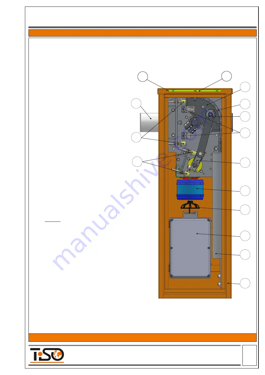
5.3 Boom Barrier mechanism design
The picture below shows the structure of right-hand boom barrier mechanism, barrier arm is in the
horizontal position, the sector of the mechanism is in the upper position, the spring is in the compressed state.
11
12
13
14
15
6
2
5
10
9
8
7
4
3
1
Legend:
1. Boom barrier cabinet;
2. Barrier arm;
3. Protective housing of spring;
4. Electronic control unit;
5. Cabinet lid;
6. Cabinet light indication;
7. Manual operation (emergency release);
8. Gear motor;
9. Gear motor lever;
10,11 Upper and lower arm movement restrictor;
12. Magnet;
13. Excentric load;
14. Chain;
15. Sector (balancing lever)
* boom barrier from protected area side
Page
-10-
Size А4
Installation and Operation Manual
Revision 1.0 2021
ROAD BLOCKING SYSTEMS
Office and Production site:
Tel.:
+380 (44) 291-21-11
14 Promyslova str., 02088, Kyiv, Ukraine,
Fax:
+380 (44) 291-21-02
E-mail:
[email protected] www.tiso.global
BOOM BARRIER OPTIMUS


