background image

3.

TINKERINE

STUDIO

STUDIO

[email protected] | 1-604-288-8778

70

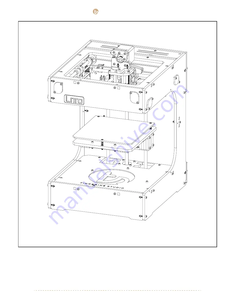
You’ve finished assembly your very own 3D printer (well almost!). With all of the components in the printer, move 
on to the next step to begging the wiring portion of the assembly.

Summary of Contents for LITTO

Page 1: ...3D Printer Creative Solution TINKERINE STUDIO ASSEMBLY MANUAL...

Page 2: ...You Start Z Platform Litto Frame pt 1 Litto Frame pt 2 Gantry pt 1 Gantry pt 2 Gantry pt 3 Carriage Electronics Spool Holder Print Bed Wiring Preliminary Run Through 3 4 6 7 8 13 21 27 38 46 50 59 67...

Page 3: ...of the hotend This air is not suitable for breathing If you feel ill from breathing while operating your 3D printer stop and seek medical attention immediately Hotend and heater cartridge become hot...

Page 4: ...TINKERINE STUDIO STUDIO support tinkerines com 1 604 288 8778 4 CARRIAGE Z AXIS THREADED ROD X AXIS BEARING CAP HOTEND COOLING FAN Y AXIS BEARING CAP Z AXIS SMOOTH ROD LITTO AT A GLANCE...

Page 5: ...E STUDIO STUDIO support tinkerines com 1 604 288 8778 5 EXTRUDER MOTOR POWER SWITCH EXTRUDER USB CONNECTION HOTEND Z AXIS PLATFORM PRINT BED PRINT COOLING FAN SPOOL HOLDER MOTOR COMPARTMENT LITTO AT A...

Page 6: ...ruder motor 1 Extruder bearing 1 Cooling fan ducts 1 Filament guiding tube 1 164mm GT2 belt 1 188mm GT2 belt 2 423mm GT2 belts 2 454mm GT2 belts 8 Brass slider bushing 8 608ZZ ball bearings 4 LM8 line...

Page 7: ...g damage by dust or blunt force To ensure proper alignment of the panel and overall rigidity of the printer it is highly recommended that the assembly is done on a flat surface Wipe off any excess gre...

Page 8: ...ts x14 x18 M3x10 Screw x4 M3x16 Screw x4 M4x20 Screw x1 45mm Bearing x2 Lead Screw Nut x1 Bearing Holder Z Arm Z Arm Z Arm 1 M3x10 x4 Tools Required M3 Allen Key M4 Allen Key Screw nut comes attached...

Page 9: ...sure the bearing is fully seated into the clip and aligned in the middle You will need two sets Similar to Step 2 take two z axis arms and wedge it into the other side of the linear bearing At this po...

Page 10: ...DIO support tinkerines com 1 604 288 8778 10 5 6 x2 x2 Arm A Arm A M3x35 x4 M3 Nut x4 One by one insert the M3 Nut into the T slots shown in the picture Screw the four M3x35 screws in but do not tight...

Page 11: ...604 288 8778 11 7 8 Arm A Arm B M3x35 x6 M3 Nut x6 Repeat step 6 and attach the second arm to the assembly Place the mid section into the respective slots on the assembly One by one insert the M3 nuts...

Page 12: ...support tinkerines com 1 604 288 8778 12 9 10 M3 Nut x4 M3x16 x4 M4x20 x1 During this point double check to make sure all panels are properly aligned and the top side of the bed is leveled with the a...

Page 13: ...y pt 1 M3 Nuts x39 Tools Required M3 Allen Key Left Side Panel Adhesive LED Strips Right Side Panel Parts Required M3x16 Screw x39 Central Back Panel Base Panel Z Constraint A Z Constraint C Bottom Fr...

Page 14: ...778 14 1 M3x16 x4 Z Constraint C Install the two Z Constraints B as shown in the picture Make sure to face the back panel the correct Insert the constraint into the corrent tabs place the M3 nuts in p...

Page 15: ...RINE STUDIO STUDIO support tinkerines com 1 604 288 8778 15 2 M3x16 x2 M3 Nut x2 Install the top Z Constraint A Similar to the bottom Z Constraint insert the piece into the slots and secure with nut s...

Page 16: ...anel FRONT BACK LED Strip x2 Using the two LED light strip supplied in your kit one by one peel off the backing to reveal the adhesive strip and stick the LED strip in the area shown in the picture Ma...

Page 17: ...8778 17 M3x16 x4 M3 Nut x4 LED Side Facing Down 3 Insert the top ring and and bottom plate into the back plate then secure with T Slots For the top ring the side with the led should be facing downward...

Page 18: ...pport tinkerines com 1 604 288 8778 18 4 Install the two side panels into the main body Secure each side with five M3x16 screws and nut Make sure the panel with the power switch cutout is on the left...

Page 19: ...nels At this point you will want to make sure all the panels are properly aligned and leveled to a flat surface Due to the natural property of wood you wooden frame may not be perfectly tapered to the...

Page 20: ...KERINE STUDIO STUDIO support tinkerines com 1 604 288 8778 20 6 Install the top and bottom brackets into the main body You will need to insert some screws from the front of the machine M3x16 x7 M3 Nut...

Page 21: ...Assembly pt 2 M3 Nuts x12 Tools Required M3 Allen Key Parts Required M3x16 Screw x6 M3x20 Screw x4 M3x25 Screw x2 x2 Z Axis Smooth Rod 270mm Z Constraint B Lead Screw NEMA17 Stepper Motor Z Constrain...

Page 22: ...e Z Axis bed and finally the top Z Constraint If you feel there is any amount of resistance once you reach the linear bearings within the z axis arms do not force it in Pull the rod backwards gently a...

Page 23: ...support tinkerines com 1 604 288 8778 23 2 M3x16 x6 M3 Nut x6 The Z Axis rods should now sit flush within the bottom and top Z Constraint Attach Z Constraint D to C secure the two pieces together with...

Page 24: ...UDIO support tinkerines com 1 604 288 8778 24 3 M3x10 x2 The Z Axis rods should now sit flush within the bottom and top Z Constraint Attach Z Constraint D to C secure the two pieces together with thre...

Page 25: ...ead screw from the bottom and into the Z Axis platform To connect the the lead screw into the nut within the platform you will need to manually turn the lead screw rod until it threads into the nut Se...

Page 26: ...the trigger you will need to different amounts of spacers with the endstop After the endstop trigger is installed Thread the wires through the holes shown in the picture Use one of the smaller adhesiv...

Page 27: ...s 8 Pieces GT2 Loop Belt 166mm Bearing x6 Pulley Small X Axis Smooth Rod 270mm x2 Y Axis Smooth Rod 255mm x2 1 Insert both ends of the belt onto the Slider B piece Make sure to line up the belt with t...

Page 28: ...TINKERINE STUDIO STUDIO support tinkerines com 1 604 288 8778 28 2 Front Slider X Axis Belt 417 mm M3x16...

Page 29: ...M3x16 X Axis Belt 417 mm TINKERINE STUDIO STUDIO support tinkerines com 1 604 288 8778 29 3 Back Slider...

Page 30: ...M3x16 Y Axis Belt 415 mm TINKERINE STUDIO STUDIO support tinkerines com 1 604 288 8778 30 Left Slider 4...

Page 31: ...TINKERINE STUDIO STUDIO support tinkerines com 1 604 288 8778 31 Right Slider 5 M3x16 Y Axis Belt 415 mm...

Page 32: ...8778 32 6 x8 Insert eight bearing into the respective slots within the frame The cutouts are meant to be a snug fit with the bearings however if you have trouble putting the bearings in there give the...

Page 33: ...X Axis Rod 270mm Back Slider Inner Bearing Cap Small Pulley Bearing With the previously assembly slider unit you will now need to add the rod pulleys inner bearing cap and depending on the slider you...

Page 34: ...4 9 10 Left Rod Right Rod Inner Bearing Cap Small Pulley Small Pulley Bearing Bearing Inner Bearing Cap Bearing Inner Bearing Cap Inner Bearing Cap Left Slider Right Slider Large Pulley Y Axis Rod 255...

Page 35: ...r the items on one by one as you insert the rods from one end For example to insert the back rod from the right side of the frame the order would be Right Inner Bearing Cap Small Pulley Back Slider La...

Page 36: ...the front side of the frame the order would be Front Inner Bearing Cap Small Pulley Back Slider Small Pulley Back Inner Bearing Cap To insert the right rod from the front side of the frame the order...

Page 37: ...all the outer bearing caps to cover the exposed bearing and prevent the rods from sliding out If you have oriented the inner bearing caps correctly in the previous steps it will align with the outer b...

Page 38: ...uired 45mm Bearing x2 B C X Axis Carriage Smooth Rod 225mm Y Axis Carriage Smooth Rod 225mm M3x50 Screw Carriage Bottom Carriage Top Linear Bearing Holder x3 M3x10 Screw x4 If your carriage comes to y...

Page 39: ...TINKERINE STUDIO STUDIO support tinkerines com 1 604 288 8778 39 1 Carriage X Axis Bearing Carriage Y Axis Bearing 2 45mm Bearing B A A A A C B C 45mm Bearing...

Page 40: ...e when inserting the smooth rod into the linear bearing Go at it slowly and make sure to not force the rod into the bearing to prevent the ball bearings from dislodging A A B C Take extra care when in...

Page 41: ...ition the carriage in the right direction Arrow on assembly pointing toward back of printer take any of the two rods and insert it carefully into the respectively linear bearing Bring the rod and carr...

Page 42: ...6 At this point this is what your gantry should look like from the top Make sure to aligned the pulleys on both sides of the belt so the belt is sitting parallel with the middle of the sliders Tighte...

Page 43: ...TINKERINE STUDIO STUDIO support tinkerines com 1 604 288 8778 43 7 M3x50 x3...

Page 44: ...rines com 1 604 288 8778 45 8 You re almost done with the gantry assembly For the most part you should now have a gantry system that you can move manually by hand Move on to part three of the gantry a...

Page 45: ...ng pulley included in the kit Follow the instruction as per the v 1 pulley Parts Required x2 v 1 v 2 x2 x2 NEMA17 Stepper Motor Motor Bracket Motor Wedge 36 Tooth Timing Pulley 18 Tooth Timing Pulley...

Page 46: ...foward or backward within the bracket to make sure the belt is tensioned and does not have extra slack Tighten the screws once the motor is in the correct position 4 Position the pulley so the belt i...

Page 47: ...avoid giving the belt any slack 3 Tighten the setscrew within the pulley on the flat edge of the motor shaft to secure the pulley 4 As shown in Step 4 take a minute to ensure that all belt are properl...

Page 48: ...8 8778 49 5 Your printer s gantry system should be fully assembled now You should be able to manually move the carriage around on the X Y axis Double check to make sure all belts are properly secures...

Page 49: ...nkerines com 1 604 288 8778 50 Carriage Assembly Tools Required M3 Allen Key Parts Required M3x16 Screw x36 Fan Shield x1 x2 Electric Fan x2 Fan Duct Extruder Assembly Hotend Assembly Ceramic Heater C...

Page 50: ...hotend to the top plate of the carriage The screws should thread into the hotend mount securing all the components together Ensure that the acrylic spacer is attached to the top of the hotend and lea...

Page 51: ...and the bottom portion of the extruder is secured to the carriage we ll now re assemble the extruder Place the spring back into the holder pin and pinch it with the top portion of the extruder Line up...

Page 52: ...ck that there is a clear path from the extruder to the nozzle The groove of the hobbed bolt should be positioned that it feeds into the hotend If the aligment of the hob is off use a allen key to loos...

Page 53: ...tive slots and secure them in place using the setscrews located on the sides of the hotend Once the thermistor and heater cartridge are in place route the wire into the wire guide shown in the pictur...

Page 54: ...ting toward the back of the printer doing so will give you cleaner look when you are perforing wire management Similar to the wires for the hotend route the fan wire up the wire guide With the M3 scre...

Page 55: ...d the hotend The fan should sit between the two carriage plates so if it does not fit you will need to loosen the carriage screws Route the fan wires so that it comes out of the top right corner and s...

Page 56: ...uder and fan assembly Double check to make sure all the fans are facing the right way and that all the wires are properly routed to go up the wire guide All components on the carraige hotend motor fan...

Page 57: ...TINKERINE STUDIO STUDIO support tinkerines com 1 604 288 8778 58 9 You are almost done assembling your printer Move on to the next step to install the power supply and electron ics to printer...

Page 58: ...bly Tools Required M3 Allen Key Parts Required Power Supply Fan Mount Power Switch Electric Socket Arduino Mega 2560 Spool Holder Motor Compartment 1 of 2 Motor Compartment 2 of 2 Back Bracket ARDUINO...

Page 59: ...M3 nut Above the power switch slot you will see another slot designated for the USB connection Using two M3x10 secure the USB head to the frame and plug in the other end into the Arduino board once i...

Page 60: ...com 1 604 288 8778 61 2 Secure the fan mount to the power supply with a M3x10 screw and mount the fan onto the fan mount using the two M3x16 screws The sticker side of the fan should be point away fro...

Page 61: ...ate You will need to use M3 nuts to secure the Arduino board Orientate the board and power supply so the ports are facing the left side of the machine M3x25 x2 M3x10 x2 The power supply is set to 110v...

Page 62: ...ll the outer bracket by securing it with the T Slots shown in the picture You may also choose to install this bracket as the last step after you have finished all the wire management doing so will giv...

Page 63: ...motor cover is composed of two pieces assemble and secure with the two T Slots on the top edge The motor cover is then secured with two T Slots on the sides The nuts on the side will require more effo...

Page 64: ...778 65 To assemble the spool holder sandwich the smaller of the three spool holder pieces with the other two and secure it with the M3 screw and M3 nut Do not tighten this yet as it will make it hard...

Page 65: ...UDIO support tinkerines com 1 604 288 8778 66 Insert the spool holder assembly to the frame and secure the spool holder with four M3 screws inserted from the front side of the printer Tighten all scre...

Page 66: ...E STUDIO STUDIO support tinkerines com 1 604 288 8778 67 Print Bed Assembly Tools Required M3 Allen Key Parts Required Print Bed Filament Guide Tube Calibration Springs Thumb Screws x3 x3 M3x25 Inset...

Page 67: ...tform Insert the inset M3x25 screw from the top and secure it with a thumb screw Repeat until you have all three points secured Turn the thumb screw to tension the spring idealy you will want the spri...

Page 68: ...ilament guide tube and thread it through the cut out located on the corner of the motor cover and motor bracket Insert the other end into the top of the extruder If you are having trouble threading th...

Page 69: ...UDIO support tinkerines com 1 604 288 8778 70 You ve finished assembly your very own 3D printer well almost With all of the components in the printer move on to the next step to begging the wiring por...

Page 70: ...ute them through the hole located on the bottom left corner of the printer This will help you indentify the wires later on NOTE 1 For the wires coming from the extruder units make sure to leave enough...

Page 71: ...KERINE STUDIO STUDIO support tinkerines com 1 604 288 8778 72 Extruder Motor X Motor Y Motor Z Motor There is a small triangle on the rightmost side Make sure it aligns as shown in the diagram IMPORTA...

Page 72: ...After you have thread the endstop wires through the black plate attach the pins into the connector housing before you plug them in Heater Cartridge Extruder Motor X Motor Y Motor Z Motor X Endstop Y...

Page 73: ...k that all sets screws on the pulley are tightened and all belts are aligned so they are seating fully in the teeths of the pulley 3 All electronics are properly plugged in and seated into their corre...

Page 74: ...rectly Do not touch hotend with your finger to check the temperature as the cartridge can be functioniing correctly while the thermistor is providing a false reading 4 Your printer is ready to start p...

Reviews: