NOTE:
The Sheave Pac assembly installation tooling shall be
manufactured as a disk/plate to allow a complete 360 degree
contact between the tool and the assembly for a uniform load
distribution during installation into the sheave bore. It is suggested
that the installation plate be hardened material to minimize
handling/storage damage.
NOTE:
Prior to use, ensure that the installation plate is in acceptable
dimensional condition and free of sharp corners, raised
material, dents, nicks, burrs, gouges, and corrosion. Any surface
imperfections should be carefully filed and/or stoned down
completely prior to use. These imperfections may cause damage to
the seal during assembly installation.
Step 9
With the bearing and seal installation initiated manually to engage the
metal-to-metal contact between the cup and the sheave, carefully
ensure that the sheave/bearing is centered under the press ram.
Step 10
Gradually inch the press ram down until it gently comes into contact with
the installation tooling without creating an impact load on the system.
Step 11
With the press ram resting on the installation tooling, gradually
increase the applied load to continue the installation of the Sheave
Pac assembly into the sheave bore until clearance is available to
install the top snap ring behind the assembly.
Step 12
With the bearing assembly installed, remove the load from the press
and remove the installation tooling.
Step 13
Install the snap rings into the sheave.
NOTE:
Limited space is available around the seal for snap ring installation.
Care must be taken to ensure seal damage is
not incurred during this snap ring installation procedure.
Step 14
Repeat Steps 1-13 as necessary for additional sheaves for a complete
block build.
B. Mounting of the Bearing/Sheave onto Pin
General Installation Information
A. Required Equipment:
• Crane/hoist and lifting/handling fixture designed to safely
handle sheaves containing a Sheave Pac assembly.
NOTE:
The Sheave Pac assembly must remain carefully aligned with the
sheave bore throughout this step in order to decrease the
potential for seal O.D. damage.
NOTE:
Before moving to the next step, ensure that the cup is completely
engaged with the sheave, as shown in Figure 2.
Step 8
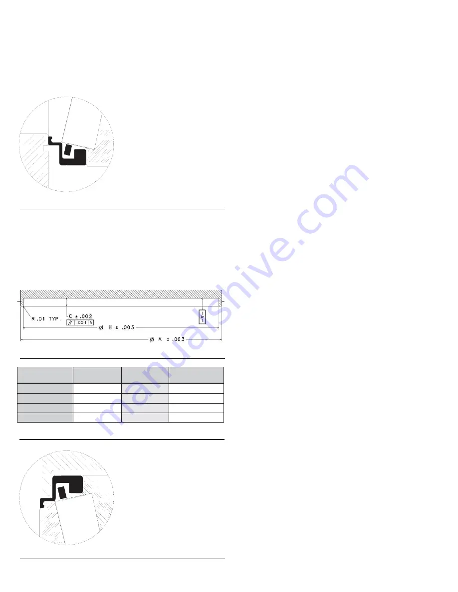
With the bearing assembly carefully centered and started into the
sheave bore entrance, carefully place size-specific installation tooling
(manufactured to meet the surrounding seal dimensional requirements
shown in Fig. 3, Fig. 4, and Fig. 5) on the top side of cup/seal interface
so as not to damage/displace seal components.
Fig. 2
Fig. 5
Assembly Bore
A (+/-0.003 in.)
B (+/- 0.003)
C (+/- 0.00 2 in.)
8 in.
10.775
10.550
0.500
10 in.
13.588
13.200
0.750
12 in.
15.400
15.000
0.610
14 in.
17.400
17.000
0.625
5
Fig. 3
Fig. 4


