


11
TiMax II MADI Interface Configuration
The MADI interface is set up through the TiMax software interface, the MADI module can be set
to master or slave and 56 or 64 channel format.
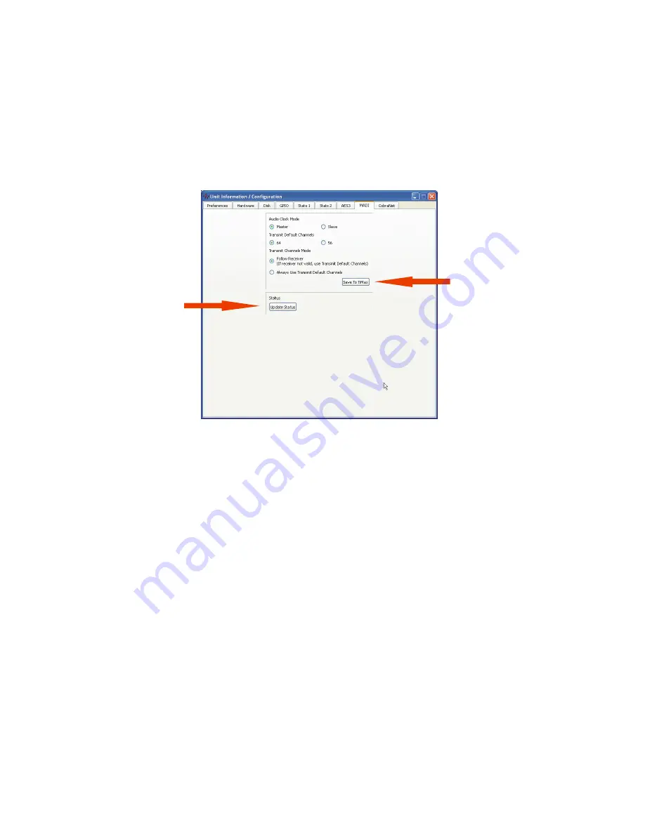
Select Unit from the menu bar and choose Unit Information / Configuration, click on the MADI
tab
Click here
to get MADI
card status
Click here
to set MADI
card status
The status of the MADI card can be seen by clicking on the Update Status button. The MADI card
status report is only updated when the Update Status button is clicked.
LED Assignment:
In addition to the reported MADI status, LEDs on the MADI card will show current status:
D1 (YEL) - Rx audio data from MADI is valid
D2 (RED) - 125 MHz Rx VCO is locked (should always be on, will lock to an internal reference if
there is no valid Rx bitstream to recover a clock from)
D3 (RED) - Power good
D4 (YEL) - ~ 250 msec blink rate, based on the audio clock (power up in slave mode with no
MADI Rx, and it will be running slow since the PLL hasn't ever had a good reference to recover
from!)
D5 (RED) - MADI Rx carrier detect