background image


MODEL 1601 SERIES COFFEE BREWER 

COMPONENT MAINTENANCE MANUAL 

WITH ILLUSTRATED PARTS LIST 


-ITEM NOT ILLUSTRATED 

25-30-27


Page 1032 

September 1, 2005 


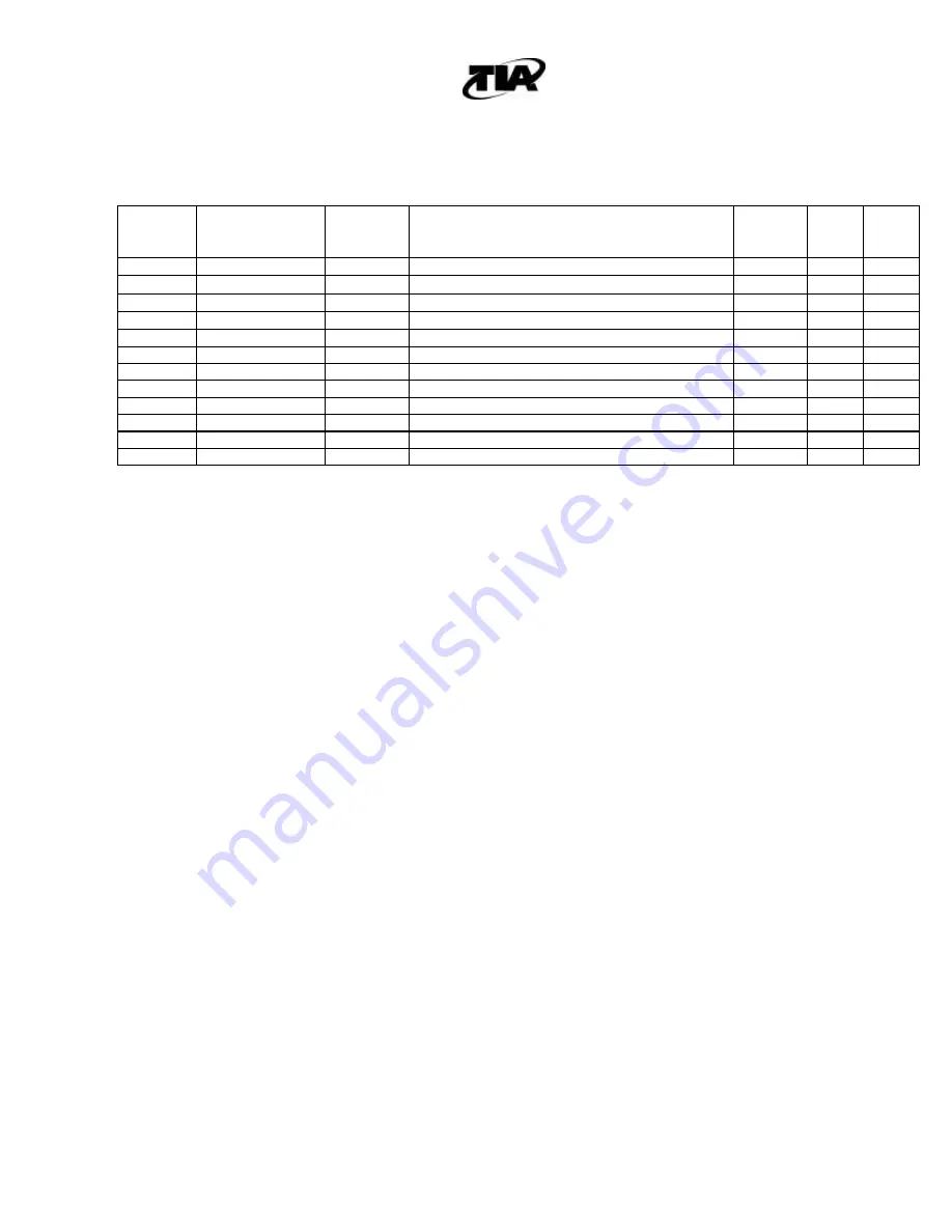
FIG/ 

ITEM 


PART NO. 

AIRLINE 

PART NO. 


DESCRIPTION/NOMENCLATURE 

1234567 

EFF 

CODE 


QTY 


U M 

1007/ 


CARAFE ASSEMBLY 


REF 

300-0873-01 


.CARAFE ASSEMBLY 


REF


1A 

300-1539-01 


.CARAFE ASSEMBLY  


REF


1B 

400-1761-01 


.CARAFE ASSEMBLY 


REF


NOT USED 


EA 

5A 

300-1538-01 


.LID TOP ASSEMBLY 

B, C 

EA 


ATTACHING PARTS 


10 

110-0218 


..SCREWS (2 PIECES) 


EA 


**** 


15 


NOT AVAILABLE 

A, C 

EA 

15A 

400-1299-01 


.CARAFE HANDLE* 

EA 


**** 


Summary of Contents for 1601A

Page 1: ...ANCE MANUAL WITH ILLUSTRATED PARTS LIST AIR COFFEE MODEL 1601 SERIES COFFEE BREWER P N 500 0521 P N 500 0619 A division of The Richards Corporation DESIGNERS AND MANUFACTURERS OF AIRCRAFT GALLEY PRODUCTS 44931 FALCON PLACE l STERLING VA 20166 USA WWW TIAPRODUCTS COM l TIA TIAPRODUCTS COM PHONE 703 471 8600 l FAX 703 481 5007 ...

Page 2: ...TED ISSUE DATE ISSUED BY REV NO PAGE INSERTED ISSUE DATE ISSUED BY 1 TP1 ROR1 LEP1 04 10 96 LOl1 LP1 1 2 101 102 103 301 302 303 304 601 602 603 604 605 606 607 608 609 610 611 701 702 703 704 1001 1002 1003 1004 1005 1006 1007 1008 1009 1010 1011 1012 1013 1014 1015 1016 1017 2 1005 1009 1012 7 15 97 3 Complete Revision 03 01 01 TIA 4 Complete Revision 09 01 05 TIA ...

Page 3: ...IES COFFEE BREWER COMPONENT MAINTENANCE MANUAL WITH ILLUSTRATED PARTS LIST 25 30 27 Page ROTR1 ROTR2 September 1 2005 RECORD OF TEMPORARY REVISIONS REV NO PAGE INSERTED ISSUE DATE INSERTED BY REMOVAL DATE REMOVED BY ...

Page 4: ...COFFEE BREWER COMPONENT MAINTENANCE MANUAL WITH ILLUSTRATED PARTS LIST 25 30 27 Page SBL1 SBL2 September 1 2005 SERVICE BULLETIN LIST SERVICE BULLETIN NUMBER REVISION NUMBER DATE BULLETIN INCORPORATED SB CB 011 A 9 01 05 ...

Page 5: ... 05 611 9 01 05 Table of Contents TOC1 9 01 05 612 9 01 05 TOC2 Blank Assembly 701 9 01 05 List of Illustrations LOl1 9 01 05 702 9 01 05 LOl2 Blank 703 9 01 05 704 Blank Leading Particulars LP1 9 01 05 LP2 Blank Special Tools Fixtures 901 9 01 05 and Equipment 902 Blank Description and 1 9 01 05 Operation 2 9 01 05 Illustrated Parts List 1001 9 01 05 3 9 01 05 1002 9 01 05 4 9 01 05 1003 9 01 05 ...

Page 6: ...age LEP2 September 1 2005 LIST OF EFFECTIVE PAGES CONT SUBJECT PAGE DATE SUBJECT PAGE DATE Illustrated Parts List 1018 9 01 05 1019 1020 9 01 05 1021 9 01 05 1022 9 01 05 1023 9 01 05 1024 9 01 05 1025 9 01 05 1026 9 01 05 1027 9 01 05 1028 9 01 05 1029 9 01 05 1030 9 01 05 1031 9 01 05 1032 9 01 05 ...

Page 7: ...September 1 2005 TABLE OF CONTENTS PARAGRAPH TITLE PAGE Description and Operation 1 Testing and Fault Isolation 101 Automatic Test Requirements N A Disassembly 301 Cleaning 401 Inspection Check 501 Repair 601 Assembly 701 Fits and Clearances N A Special Tools Fixtures and Equipment 901 Illustrated Parts List 1001 ...

Page 8: ...am 1601 DC28 608 606 Wiring Diagram 1601A DC28 609 607 Wiring Diagram 1601B DC28 1601B DC28 B 610 608 Plumbing Diagram Model 1601 611 609 Plumbing Diagram Models 1601A and 1601B 612 1001 Illustrated Parts List P N 500 0521 Model 1601 Series Coffee Brewer 1013 1014 1002 Illustrated Parts List P N 500 0619 Model 1601A and 1601B Series Coffee Brewer 1019 1020 1003 Illustrated Parts List Heater Assemb...

Page 9: ...GLE PHASE 60 400 HZ 1000 WATTS 1601A AC3P 1601B AC3P 115 VAC 3 PHASE 300 700 HZ 1000 WATTS 1601B AC1P 115 VAC 3 PHASE 300 700 HZ 1000 WATTS 1601 DC28 1601A DC28 1601B DC28 1601B DC28 B 28 VOLTS DC 1000 WATTS 3 WEIGHT A 1601 EMPTY 11 00 Lbs B 1601A EMPTY 9 50 Lbs C 1601B EMPTY 9 50 Lbs 4 BREW CHARACTERISTICS A Capacity 48 oz 10 cups B Coffee Temperature 170 180º F C Brew Temperature 190º F D Brew T...

Page 10: ...osed compartment Compartment doors should be open during operation to prevent a build up of heat and humidity 2 Description A A single POWER switch operates the unit and when in the ON position allows the water to be heated to a point controlled by the control thermostat at which the heated water percolates up the brew pipe over the coffee in the brew tray and into the carafe B A manually resettab...

Page 11: ...cle NOTE Only pour fresh water into the water tank Do not pour coffee or other premixed liquids into the water tank Doing so will result in damage to the coffee brewer C Switch coffee brewer ON The indicator light will illuminate on units equipped with indicator lights P N 500 0521 01 02 and 500 0619 01 02 ONLY After approximately 30 seconds water will start percolating through the brew basket and...

Page 12: ...F FREEZING TEMPERATURES ARE EXPECTED AND COFFEE BREWER WILL NOT BE IN USE COFFEE BREWER WATER SYSTEM MUST BE DRAINED TO PREVENT ICE DAMAGE SEE DRAINING COFFEE BREWER A Draining Coffee Brewer 1 There is no manual drain on the 1601 Series Coffee Brewer To drain the water from the coffee brewer switch the coffee brewer ON and operate the coffee brewer until the water tank is empty 2 Turn coffee brewe...

Page 13: ...tainer originally provided by the manufacturer NOTE Inserts may be stacked in accordance with standard warehouse practices 4 If inserts are to be stacked a separator of inch plywood or similar protective device is to be placed between the units to insure against damage to the finish or component parts B Short Duration Storage NOTE No special protection is required if the units are to be stored les...

Page 14: ...de and assumes that all internal wiring and power connections are correct B The 1601 series coffee brewers have single setpoint thermostats Brew temperature calibration is not adjustable The thermostat does not control the brew temperature it controls the temperature of the heater block 2 Testing A Functional Test Setup The test bench will require the following 1 Power Requirements MODEL TEST BENC...

Page 15: ...urrent Draw 1601 AC3P 1601A AC3P 1601B AC3P 2 9 Amps 0 5 Amps 1601B AC1P 8 5 Amps 1 Amp 1601 DC28 1601A DC28 1601B DC28 1601B DC28 B 35 Amps 3 Amps 5 Water will now be heated and dispensed through the brew tray into the carafe The time to complete a brew cycle is approximately 8 10 minutes NOTE In certain circumstances coffee brewers equipped with 300 thermostats can experience extended brew cycle...

Page 16: ...ng Guide These guides address the most common potential problems associated with these models It is not intended to solve more in depth faults A All Model 1601 Series Fault Probable Cause Effectivity 1 After the brew cycle is completed and carafe has been sitting on the warmer tray unit switches off and will not switch back on a The overheat thermostat has disconnected power from the heaters Allow...

Page 17: ... for repair or replace heater element c Water and or unit was very cold when starting brew The water took longer to heat resulting in a longer brew time All 5 ON OFF switch is ON but unit will not brew a The power relay is defective b Overheat thermostat has tripped All 6 Power Indicator on ON OFF switch does not light Brewer works otherwise Indicator lamp in switch is defective Replace switch 500...

Page 18: ...play LEDs are erratic and do not function normally a Check source of water If water is distilled display may not work correctly because of low mineral content of water b Malfunctioning Display PCB Assembly Replace assembly with a known good PCB assembly and retest c Faulty cold water tank probe Return to TIA for repair or repair as necessary 500 0619 Models Only ...

Page 19: ...MODEL 1601 SERIES COFFEE BREWER COMPONENT MAINTENANCE MANUAL WITH ILLUSTRATED PARTS LIST 25 30 27 Page 106 September 1 2005 THIS PAGE INTENTIONALLY LEFT BLANK ...

Page 20: ... section consists of the following subsections a Disassembly instructions for Model 1601 b Disassembly instructions for Models 1601A and 1601B NOTE Observe proper ESD handling and storage procedures for PCB assemblies after removing top cover ESD Discharges may damage PCB assemblies 2 Disassembly Instructions for Model 1601 A Top Cover and Cold Water Tray Disassembly Figure 1001 1 Remove top cover...

Page 21: ...5 by removing screws 290 2 Disconnect electrical leads from the heater assembly 100 as necessary 3 Remove locknuts 115 screws 110 and heater clamp 105 4 Remove heater assembly 100 from chassis 5 5 Remove tray 90 and gasket 95 from chassis 5 E Heater Disassembly Figure 1003 1 Remove screws 20 and washer 25 from heater casting 5 Remove overheat thermostat 10 2 Remove screws 40 and washer 45 from hea...

Page 22: ... tube 3 Remove screws 385 and remove water tank 380 from chassis 5 Liquid Level sensor and ground wires will still be connected Support water tank 4 Remove ground and liquid level sensor leads from water tank 380 by removing screws 390 and split lockwashers 395 C Brew Head Disassembly Figure 1002 1 Remove brew tube 290 from barbed adapter 55 2 Remove brew head 40 from chassis 5 by removing screws ...

Page 23: ...d gasket 230 from chassis 5 E 1601A Heater Disassembly Figure 1003 1 Remove screws 20 and washer 25 from heater casting 5 Remove overheat thermostat 3 2 Remove screws 40 and washer 45 from heater casting 1 5 Remove control thermostat 40 NOTE Heater elements 50 are staked in place and should not be removed except for replacement of a failed element F 1601B Heater Disassembly Figure 1003 A Remove sc...

Page 24: ...ccur at regular intervals based on operator s experience NOTE The primary cause of slow brew cycles is the buildup of mineral deposits in the heater block Method 1 1 Operate coffee brewer until water tank is empty NOTE Handle with care as unit may be hot 2 Flush mineral deposits from the brew system using an automatic coffee brewer cleaning solution available from local retail outlets Cycle cleani...

Page 25: ...led vinegar 3 Leave distilled vinegar in coffee brewer for twelve hours 4 Brew several pots of clean water to flush vinegar and residue from system 5 Clean all external surfaces using warm water Particular care must be taken to remove coffee residue that may have accumulated within the moving areas such as the pot retainer Mild soap may be used if necessary ...

Page 26: ... the function of the equipment 2 Electrical A Inspect electrical wiring and connection points for damage deteriorated insulation and loose wires B Check coffee brewer connector for loose bent or broken pins deformed shell or evidence of arcing of flashover at pin insert insulation C Check terminal strip for cracked insulation and loose terminals D Check switch function check open and closed positi...

Page 27: ...al coffee brewer parts which contain small orifices may become clogged and require disassembly and or cleaning Use of hard water will also leave scale deposits which slowly clog the system Any evidence of water stoppage or slower than normal water flow requires inspection of these critical parts for malfunction 4 Power Switch Replacement Applicable to Part Numbers 500 0619 01 02 ONLY that use a po...

Page 28: ... relay thermostats and power switch 6 Thermostats Applicable to P N 500 0619 only A Three Control thermostats with three different temperature set points were used during the production life of the Model 1601 Series coffee brewer TIA P N 500 0619 B The temperature changes were made to vary the holding temperature of the coffee The temperature difference between the thermostats WILL NOT affect the ...

Page 29: ...T CONDITION IS NOT AN INDICATION OF A COFFEE BREWER FAULT A There is one overheat thermostat on this coffee brewer The thermostat is located on the heater assembly for the 1601 and 1601A units On 1601B units the overheat thermostat is located on the thermostat mounting plate B Use the tip of a non conductive pen sized device to press the button in the center of the thermostat to manually reset it ...

Page 30: ...MODEL 1601 SERIES COFFEE BREWER COMPONENT MAINTENANCE MANUAL WITH ILLUSTRATED PARTS LIST 25 30 27 Page 604 September 1 2005 Figure 601 Wiring Diagram Model 1601 AC3P ...

Page 31: ...MODEL 1601 SERIES COFFEE BREWER COMPONENT MAINTENANCE MANUAL WITH ILLUSTRATED PARTS LIST 25 30 27 Page 605 September 1 2005 Figure 602 Wiring Diagram Model 1601B AC1P ...

Page 32: ...MODEL 1601 SERIES COFFEE BREWER COMPONENT MAINTENANCE MANUAL WITH ILLUSTRATED PARTS LIST 25 30 27 Page 606 September 1 2005 Figure 603 Wiring Diagram Model 1601A AC3P Illuminated Switch ...

Page 33: ...ODEL 1601 SERIES COFFEE BREWER COMPONENT MAINTENANCE MANUAL WITH ILLUSTRATED PARTS LIST 25 30 27 Page 607 September 1 2005 Figure 604 Wiring Diagram Model 1601A AC3P Non Illuminated Switch and 1601B AC3P ...

Page 34: ...MODEL 1601 SERIES COFFEE BREWER COMPONENT MAINTENANCE MANUAL WITH ILLUSTRATED PARTS LIST 25 30 27 Page 608 September 1 2005 Figure 605 Wiring Diagram Model 1601 DC28 ...

Page 35: ...MODEL 1601 SERIES COFFEE BREWER COMPONENT MAINTENANCE MANUAL WITH ILLUSTRATED PARTS LIST 25 30 27 Page 609 September 1 2005 Figure 606 Wiring Diagram Model 1601A DC28 Illuminated Switch ...

Page 36: ...MODEL 1601 SERIES COFFEE BREWER COMPONENT MAINTENANCE MANUAL WITH ILLUSTRATED PARTS LIST 25 30 27 Page 610 September 1 2005 Figure 607 Wiring Diagram Model 1601B DC28 and 1601B DC28 B ...

Page 37: ...MODEL 1601 SERIES COFFEE BREWER COMPONENT MAINTENANCE MANUAL WITH ILLUSTRATED PARTS LIST 25 30 27 Page 611 September 1 2005 Figure 608 Plumbing Diagram Model 1601 ...

Page 38: ...MODEL 1601 SERIES COFFEE BREWER COMPONENT MAINTENANCE MANUAL WITH ILLUSTRATED PARTS LIST 25 30 27 Page 612 September 1 2005 Figure 609 Plumbing Diagram Model 1601A and 1601B ...

Page 39: ...his manual 2 Assembly Instructions for Model 1601 A Top Cover and Cold Water Tray Assembly Figure 1001 1 Install receptacle 15 to top cover 10 with screws 20 2 Align gasket 30 onto cold water tray 25 3 Install top cover 10 top cover gasket 30 and cold water tray 25 with screws 35 B Water Tank Assembly Figure 1001 1 Install sight gauge tube 200 into fitting 205 2 Attach water tank 355 with screws 3...

Page 40: ...ly Installation Figure 1001 1 Install tray 90 and gasket 95 to chassis 5 2 Position heater assembly 100 and clamp 105 to chassis 5 and Install screws 110 and locknuts 115 3 Reconnect all electrical leads for the heater assembly 100 to their terminal board 275 locations 4 Install bottom cover 285 using screws 290 3 Assembly Instructions for Model 1601A and 1601B A Top Cover and Cold Water Tray Asse...

Page 41: ...n Models 1601B coffee brewers apply thermal grease 250A to mating surfaces install overheat thermostat 245A onto thermostat mounting plate 240 using locknut 255 3 On Model 1601B Coffee Brewers apply thermal grease 250A to thermostat mounting plate 240A and position over heater assembly 260 4 Position heater assembly 260 and clamp 270 into chassis and install screws 265 and locknuts 275 5 On Models...

Page 42: ...g surfaces and Install control thermostat 30 onto heater casting 5 using screws 40 and washer 45 2 Apply thermal grease 15 to mating surfaces and Install overheat thermostat 10 onto heater casting 5 using screws 20 and washer 25 F Model 1601B Heater Assembly Figure 1003 1 Apply thermal grease 35 to mating surfaces and Install control thermostat 40 onto heater casting 15 using screws 40 and washer ...

Page 43: ...ich may be required for the installation repair or maintenance of the Model 1601 Series Coffee Brewers are listed below TIA recommends that all test equipment be calibrated prior to use Equivalent substitutes may be used Tool Specification or Model Source Volt Ohm Meter Model 8060A V4U744 Thermocouple Probe Model HH506R V29907 See IPL Vendor s Code List for vendor name and addresses ...

Page 44: ...guish parts Refer to the EFF CODE column for the item and use the part with the corresponding effectivity code C How to Use This Parts List 1 When ordering parts from TIA the TIA part number when referenced in the Description column must be listed on the purchase order document Failing to do so may result in delays in order processing 2 When the part number is not known locate the part on the illu...

Page 45: ...on of Models TIA PART NUMBER MODEL NUMBER DESCRIPTION 500 0521 01 1601 AC3P 115 VAC 3 40 600 HZ 1000W 500 0521 02 1601 DC28 28 VDC 1000W 500 0619 01 1601A AC3P 115 VAC 3 300 700 HZ 1000W 500 0619 02 1601A DC28 28 VDC 1000W 500 0619 03 1601B DC28 B 28 VDC 1000W ALL BLACK 500 0619 04 1601B AC3P 115 VAC 3 300 700 HZ 1000W BLACK CARAFE WITH LID 500 0619 05 1601B DC28 28 VDC 1000W BLACK CARAFE WITH LID...

Page 46: ...841 Railroad St Corona CA 91720 V 4251X B F Goodrich 500 South Main Street Akron OH 44318 V 25628 BUNN O MATIC Corporation 1400 Stevenson Drive Springfield IL 62703 4291 USA V 73559 Carling Switch Inc 60 Johnson Ave Plainville CT 06062 1177 V 05668 Cole Parmer Instrument Co 7425 North Oak Pack Ave Niles IL 60714 V 72512 Davies Molding Co 350 E Kehoe Blvd Carol Stream IL 60188 V 14604 Elmwood Senso...

Page 47: ...0 Lemona Ave Van Nuys CA 91409 9234 V 75382 Kulka Inc 1913 Atlantic Avenue Manasquan NJ 08736 V 05972 Loctite Corporation 1001 Trout Brook Xing Rocky Hill CT 06067 3582 USA V 13764 Micro Plastics Inc Hwy 178 N Flippin AR 72634 V 92678 Wakefield Engineering Inc 60 Audubon Road Wakefield MA 01880 V 79221 Watlow Electric Mfg Co 12001 Lackland Rd St Louis MO 63146 Commercial and Government Entity Code...

Page 48: ...10 0221 1001 255 24 EA 1002 290 24 EA 110 0223 1001 200 6 EA 110 0224 1001 45 1 EA 1002 55 1 EA 110 0226 1001 170 1 EA 110 0246 1001 205 2 EA 120 8 1002 250A A R EA 1003 15 AR EA 1003 35 A R EA 120 0076 1003 50 2 EA 120 0085 1003 50B 2 EA 121 0063 1001 295 2 EA 121 0063 1002 365 2 EA 121 0065 1001 295A 2 EA 1002 365A 2 EA 121 0067 1001 300A 2 EA 1002 360A 2 EA 121 0068 1001 300 2 EA 1002 360 2 EA ...

Page 49: ...6 0299 1002 165A 2 EA 126 0426 1002 85 2 EA 126 0449 1002 60 1 EA 135 0041 1001 360 4 EA 1002 385 4 EA 135 0186 1001 115 2 EA 1002 275 2 EA 135 0199 1001 345 2 EA 135 0235 1002 90 2 EA 135 0276 1001 215 4 EA 1002 140 4 EA 135 0380 C24 1001 225 2 EA 1001 145 2 EA 1002 190 2 EA 135 0380 C26 1002 125 2 EA 1001 240 2 EA 1002 285 10 EA 1001 290 10 EA 1002 375 4 EA 135 0380 C27 1002 25 12 EA 1001 35 14 ...

Page 50: ...35 0381 13 1002 180 4 EA 135 0381 15 1001 135 4 EA 1001 310 2 EA 135 0381 16 1001 320 4 EA 1002 330 4 EA 135 0381 2 1003 20 2 EA 1003 40 2 EA 135 0381 28 1002 70 4 EA 135 0381 30 1002 390 5 EA 135 0382 61 1002 205 2 EA 135 0382 63 1001 335 2 EA 1002 345 2 EA 135 0383 C2 1003 25 2 EA 1003 45 2 EA 135 0383 D10L 1001 340 6 EA 1002 350 4 EA 135 0384 136 1002 320 12 EA 1002 75 4 EA 1002 395 21 EA 135 0...

Page 51: ...001 365 1 EA 150 1132 01 1001 95 1 EA 1002 230 1 EA 150 1141 01 1001 165 1 EA 150 1157 01 1001 130 2 EA 1002 175 2 EA 150 1190 01 1001 195 1 EA 150 1236 01 1002 100 1 EA 150 1239 01 1002 200 1 EA 200 0349 01 1002 135 1 EA 1001 210 1 EA 200 0807 01 1001 305 1 EA 200 1097 01 1002 120 1 EA 1001 235 1 EA 200 1141 01 1001 105 1 EA 1002 270 1 EA 200 1142 01 1002 145 1 EA 1001 220 1 EA 200 1143 01 1001 1...

Page 52: ... 300 1333 01 1001 140 1 EA 1002 185 1 EA 300 1358 01 1002 280 1 EA 1001 285 1 EA 300 1359 01 1001 70 1 EA 300 1359 02 1001 60 1 EA 300 1360 01 1001 175 1 EA 300 1361 01 1001 150 1 EA 300 1403 01 1001 100 1 EA 1002 260 1 EA 300 1403 02 1002 260A 1 EA 300 1403 03 1002 260B 1 EA 300 1403 04 1002 260C 1 EA 300 1482 01 1002 65 1 EA 300 1482 02 1002 65A 1 EA 300 1525 01 1002 240A 1 EA 300 1538 01 1007 5...

Page 53: ... 1002 5 1 EA AN960 C2 1003 25 2 EA 1003 45 2 EA AN960 D10L 1001 340 6 EA 1002 350 4 EA J2J174A 1003 50A 2 EA J2JX319A 1003 50 2 EA MS12883 40 14 1001 300 2 EA 1002 360 2 EA MS12883 48 01 1001 300A 2 EA 1002 360A 2 EA MS21042 04 1001 330 4 EA 1002 340 4 EA 1002 255A 4 EA MS21042 06 1002 35 2 EA 1001 275 4 EA 1002 315 2 EA MS21042 3 1002 355 2 EA 1002 210A 2 EA MS24693 C24 1001 225 2 EA 1001 145 2 E...

Page 54: ...MS24693 C7 1001 160 4 EA 1001 185 4 EA MS3102R18 8P 1001 315A 1 EA 1002 325 1 EA MS3102R18 11P 1002 325A 1 EA MS35338 136 1002 320 12 EA 1002 75 4 EA 1002 395 21 EA MS51957 13 1002 180 4 EA MS51957 15 1001 135 4 EA 1001 310 2 EA MS51957 16 1001 320 4 EA 1002 330 4 EA MS51957 2 1003 20 2 EA 1003 40 2 EA MS51957 28 1002 70 4 EA MS51957 30 1002 390 5 EA MS51958 61 1002 205 2 EA MS51958 63 1001 335 2 ...

Page 55: ...MODEL 1601 SERIES COFFEE BREWER COMPONENT MAINTENANCE MANUAL WITH ILLUSTRATED PARTS LIST 25 30 27 Page 1012 September 1 2005 THIS PAGE INTENTIONALLY LEFT BLANK ...

Page 56: ...L 1601 SERIES COFFEE BREWER COMPONENT MAINTENANCE MANUAL WITH ILLUSTRATED PARTS LIST 25 30 27 Page 1013 1014 September 1 2005 Figure 1001 Model 1601 Series Coffee Brewer Illustrated Parts List P N 500 0521 ...

Page 57: ...REW 6 32 x 7 16 FHMS TIA P N 135 0380 C27 14 EA 40 400 1109 01 HOT WATER RECEPTACLE 1 EA ATTACHING PARTS 45 110 0224 BARBED ADAPTER 1 EA 50 300 1331 01 FILTER BASKET SUPPORT 1 EA ATTACHING PARTS 55 MS24693 C29 SCREW 6 32 x 5 8 FHMS TIA P N 135 0380 C29 4 EA 60 300 1359 02 FRONT BASKET SUPPORT R H 1 EA ATTACHING PARTS 65 MS24693 C3 SCREW 4 40 x 5 16 FHMS TIA P N 135 0380 C3 3 EA 70 300 1359 01 FRON...

Page 58: ... 1 EA ATTACHING PARTS 145 MS24693 C24 SCREW 6 32 x 1 4 FHMS TIA P N 135 0380 C24 2 EA 150 300 1361 01 LIQUID LEVEL CAP 1 EA ATTACHING PARTS 155 126 0075 SILICONE O RING 2 EA 160 MS24693 C7 SCREW 4 40 x 5 8 FHMS TIA P N 135 0380 C7 4 EA 165 150 1141 01 LIQUID LEVEL TUBE 1 EA 170 110 0226 POLYPROPYLENE BALL 1 EA 175 300 1360 01 LIQUID LEVEL BASE 1 EA 180 NOT USED EA ATTACHING PARTS 1 185 MS24693 C7 ...

Page 59: ...G PARTS 265 137 0109 MARKER STRIP 2 EA 270 MS24693 C29 SCREW 6 32 x 5 8 FHMS TIA P N 135 0380 C29 4 EA 275 MS21042 06 6 LOCKNUT TIA P N 135 0385 06 4 EA 280 126 0069 JUMPER 2 EA 285 300 1358 01 BOTTOM COVER 1 EA ATTACHING PARTS 290 MS24693 C26 SCREW 6 32 x 3 8 FHMS TIA P N 135 0380 C26 10 EA 295 M83536 17 005L RELAY TIA P N 121 0063 A 2 EA 295A 121 0065 RELAY 25 AMP 28V 3 PDT B 2 EA ATTACHING PART...

Page 60: ...IA MODEL 1601 SERIES COFFEE BREWER REF 335 MS51958 63 GROUND SCREW 10 32 x PHMS TIA P N 135 0382 63 A 2 EA 335A NOT USED B EA ATTACHING PARTS 340 AN960 D10L 10 FLAT WASHER TIA P N 135 0383 D10L A 6 EA 340A NOT USED B EA 345 MS21042 6 10 LOCKNUT TIA P N 135 0385 3 A 2 EA 345A NOT USED B EA 350 NOT USED EA 355 500 0527 01 COLD WATER TANK 1 EA ATTACHING PARTS 360 135 0041 SCREW 6 32 x 3 8 HEX HD MS 4...

Page 61: ...MODEL 1601 SERIES COFFEE BREWER COMPONENT MAINTENANCE MANUAL WITH ILLUSTRATED PARTS LIST 25 30 27 Page 1019 1020 September 1 2005 ...

Page 62: ...3P COFFEE BREWER J REF 5 500 0621 01 CHASSIS 1 EA 10 200 1275 01 TOP COVER ASSY 1 EA 15 RTV 103 BLACK R T V V 01139 A R EA 20 400 1234 01 COLD WATER TRAY 1 EA ATTACHING PARTS 25 MS24693 C27 SCREW 6 32 x 7 16 FHMS TIA P N 135 0380 C27 12 EA 30 DELETED EA 35 MS21042 06 6 LOCKNUT TIA P N 135 0385 06 2 EA 40 200 1221 01 BREW HEAD SB CB 011 1 EA ATTACHING PARTS 45 RTV 103 BLACK R T V V 01139 A R EA 50 ...

Page 63: ...135 NAMEPLATE NOT FOR SALE 1 EA ATTACHING PARTS 140 135 0276 POP RIVET DOME HD 4 EA 145 200 1142 01 CARAFE BUMPER 1 EA ATTACHING PARTS 150 135 0380 C3 SCREW 4 40 x 5 16 FHMS TIA P N 135 0380 C3 2 EA 155 200 1143 01 POT RETAINER ASSEMBLY A B 1 EA 155A 200 1305 01 POT RETAINER ASSEMBLY C D E F G H J 1 EA ATTACHING PARTS 160 126 0259 BALL KNOB 1 EA 165 NOT USED A B 0 EA 165A 126 0299 VINYL CAP C D E ...

Page 64: ...A 220B 400 1761 01 CARAFE ASSEMBLY J 1 EA 225 300 1324 01 TRAY A B 1 EA 225A 200 1301 01 TRAY C D E F G H J 1 EA 230 150 1132 01 GASKET 1 EA 235 RTV 108 CLEAR RTV ADHESIVE V 01139 A R EA 240 NOT USED A B 0 EA 240A 300 1525 01 MOUNTING PLATE THERMOSTAT C D E F G H J 1 EA ATTACHING PARTS 245 NOT USED A B EA 245A 125 0042 OVERHEAT THERMOSTAT C D E F G H J 1 EA 250 NOT USED A B EA 250A 120 8 THERMAL G...

Page 65: ...UT TIA P N 135 0385 06 2 EA 320 MS35338 136 6 SPLITLOCK WASHER TIA P N 135 0384 136 12 EA 325 MS3102R18 8P CONNECTOR TIA P N 136 0024 A D F G H J 1 EA 325A MS3102R18 11P CONNECTOR TIA P N 136 0051 B C E 1 EA ATTACHING PARTS 330 MS51957 16 SCREW 4 40 x 7 16 PHMS TIA P N 135 0381 16 4 EA 335 DELETED 4 WASHER EA 340 MS21042 04 4 LOCKNUT TIA P N 135 0385 04 4 EA 345 MS51958 63 GROUND SCREW 10 32 x 1 2...

Page 66: ...234567 EFF CODE QTY U M 1002 500 0619 TIA MODEL 1601 SERIES COFFEE BREWER REF 370 400 1240 01 RELAY CONNECTOR BRACKET 1 EA 375 MS24693 C26 SCREW 6 32 x 3 8 FHMS TIA P N 135 0380 C26 4 EA 380 400 1233 01 COLD WATER TANK 1 EA ATTACHING PARTS 385 135 0041 SCREW 6 32 x 3 8 HEX HD MS 4 EA 390 MS51957 30 SCREW 6 32 x 1 2 PHMS TIA P N 135 0381 30 5 EA 395 MS35338 136 6 SPLITLOCK WASHER TIA P N 135 0384 1...

Page 67: ...MODEL 1601 SERIES COFFEE BREWER COMPONENT MAINTENANCE MANUAL WITH ILLUSTRATED PARTS LIST ITEM NOT ILLUSTRATED 25 30 27 Page 1026 September 1 2005 Figure 1003 Illustrated Parts List Heater Assembly ...

Page 68: ... MACHINED A B C D E 1 EA 10 125 0042 OVERHEAT THERMOSTAT A B 2 EA 10A NOT USED C D E EA ATTACHING PARTS 15 120 8 THERMAL GREASE V 92678 AR EA 20 MS51957 2 SCREW PH MACH 2 56x3 16 TIA P N 135 0381 2 A B 2 EA 20A NOT USED C D E 25 AN960 C2 FLATWASHER 2 TIA P N 135 0383 C2 A B 2 EA 25A NOT USED C D E 30 125 0046 CONTROL THERMOSTAT 1 EA ATTACHING PARTS 35 120 8 THERMAL GREASE V 92678 A R EA 40 MS51957...

Page 69: ...MODEL 1601 SERIES COFFEE BREWER COMPONENT MAINTENANCE MANUAL WITH ILLUSTRATED PARTS LIST ITEM NOT ILLUSTRATED 25 30 27 Page 1028 September 1 2005 Figure 1004 DELETED MOVED TO FIGURE 1003 ...

Page 70: ...MODEL 1601 SERIES COFFEE BREWER COMPONENT MAINTENANCE MANUAL WITH ILLUSTRATED PARTS LIST ITEM NOT ILLUSTRATED 25 30 27 Page 1029 September 1 2005 Figure 1005 DELETED MOVED TO FIGURE 1001 ...

Page 71: ...MODEL 1601 SERIES COFFEE BREWER COMPONENT MAINTENANCE MANUAL WITH ILLUSTRATED PARTS LIST ITEM NOT ILLUSTRATED 25 30 27 Page 1030 September 1 2005 Figure 1006 DELETED MOVED TO FIGURE 1001 ...

Page 72: ...MODEL 1601 SERIES COFFEE BREWER COMPONENT MAINTENANCE MANUAL WITH ILLUSTRATED PARTS LIST ITEM NOT ILLUSTRATED 25 30 27 Page 1031 September 1 2005 Figure 1007 Illustrated Parts List Carafe Assembly ...

Page 73: ...RLINE PART NO DESCRIPTION NOMENCLATURE 1234567 EFF CODE QTY U M 1007 CARAFE ASSEMBLY REF 1 300 0873 01 CARAFE ASSEMBLY A REF 1A 300 1539 01 CARAFE ASSEMBLY B REF 1B 400 1761 01 CARAFE ASSEMBLY C REF 5 NOT USED A EA 5A 300 1538 01 LID TOP ASSEMBLY B C 1 EA ATTACHING PARTS 10 110 0218 SCREWS 2 PIECES 2 EA 15 NOT AVAILABLE A C 1 EA 15A 400 1299 01 CARAFE HANDLE B 1 EA ...

Reviews: