


Rev B Sept 2020
Page 41
Chapter 5 PC Operation - Tutorial
C.1.3 Circle Size and Gain Control
Given that movement of two opposing fibers produces variations in the coupled power, the very act of automatically aligning
the fibers to increase the coupled power may cause unwanted disturbances to the signal path.
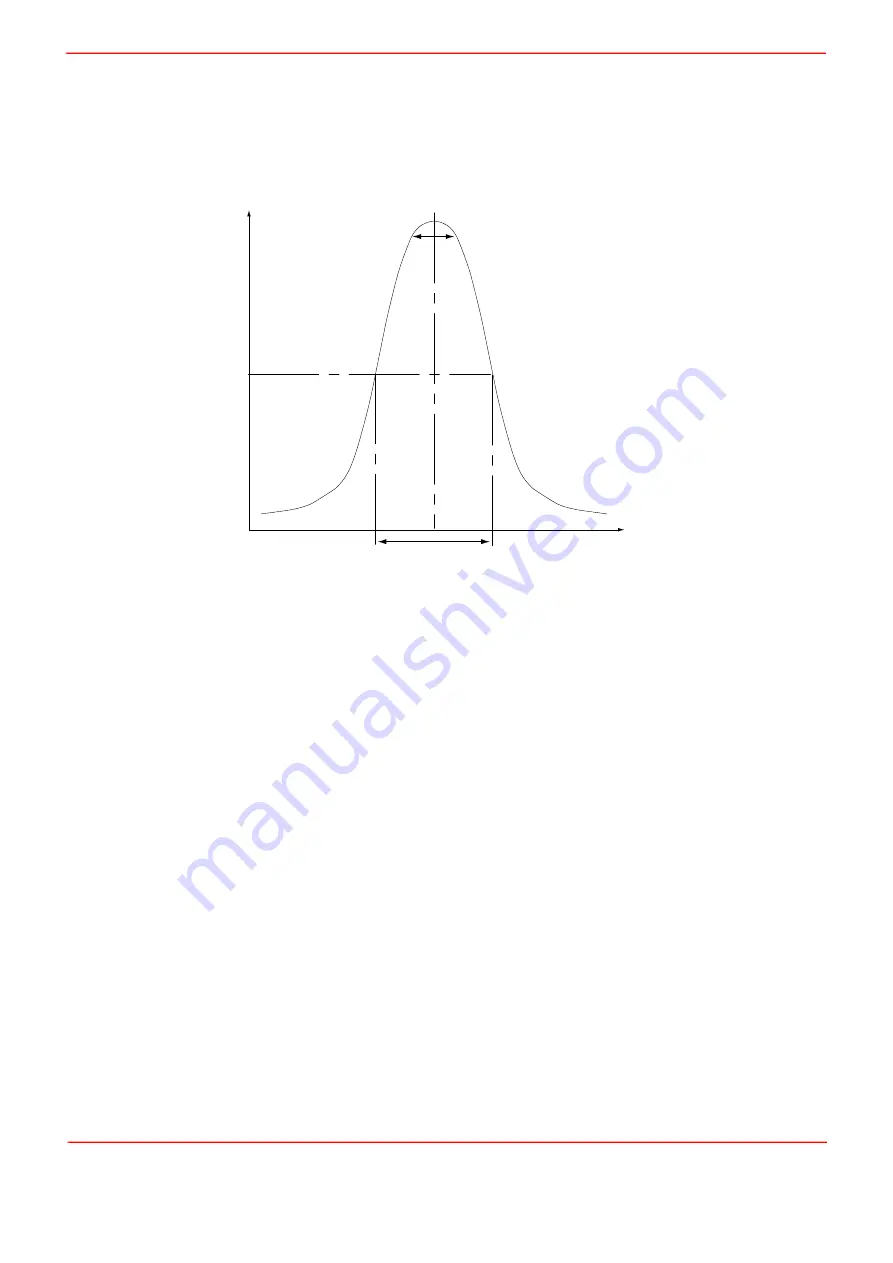
Consider the optical profile in Fig. C.5. When the NanoTrak is tracking, the polarity of the resultant control voltage is
determined by the position of the aligning fiber relative to the center line and the voltage amplitude is proportional to the amount
of displacement from this center line.
Fig. C.5 Circle diameter
If the scan circle diameter ‘d’ is such that the circle crosses the center line, the polarity of the control voltage is reversed and
movement of the circle becomes erratic. The ideal circle size is dependant upon the shape and dimensions of the optical curve
associated with a particular application, but should be between
1
/
10
and
1
/
20
FWHM (full width half maximum).
Under normal operation, the circle size should be reduced in proportion to the coupled signal, from a maximum of 3 µm to a
value of less than 50 nm. At the point of optimized alignment, this small modulating signal results in a small AC component,
sufficient to maintain tracking but low enough to ensure that the resultant modulation does not interfere with the measurement
being made.
The circle size can be set manually by entering a value in the Settings panel. Alternatively, if automatic LUT diameter
adjustment mode is enabled, the system uses values in a LUT to modify circle diameter in relation to the input range currently
selected.
This LUT diameter adjustment mode allows appropriate circle diameters to be applied on an application specific basis.
The loop gain can also effect system stability. If the gain is too high, the circle moves erratically, whereas too low a setting
results in the circle ‘floating’ around the edge of the screen. Loop gain can be configured from the Controller GUI.
Both circle size and loop gain effect the system amplification. As a guide to manual settings, if the scan circle moves erratically
round the screen, the amplification should be reduced, and conversely, if the scan circle movement is sluggish, the
amplification should be increased. As with any phase locked control loop, it may be necessary to perform application-specific
adjustments to optimize the speed of response and stability.
C.1.4 Phase Offset
Theoretically, if the NanoTrak were to read the power and respond by moving the fiber instantaneously, the power signal read
in would be in phase with the modulating signal. In reality, the various electronic and electromechanical components (e.g.
power meters, piezo actuators) within the control loop can introduce delays which means that the NanoTrak is always reacting
to a power reading which was taken in the past. This, in turn, can cause a phase shift and, in extreme cases, can lead to
instability.
A phase offset can be introduced to compensate for any phase shifts. In the system, a different phase offset can be specified
for each axis of motion. This is particularly useful in those mechanical systems that exhibit different delays in different
directions.
coupled power
fiber displacement
50%
FWHM
d
Summary of Contents for NanoTrak KNA-IR
Page 47: ...www thorlabs com ...


