


Rev B Sept 2020
Page 25
Chapter 5 PC Operation - Tutorial
Error LED
— Lit when a fault condition occurs, i.e. either a power supply voltage is out of range, or a channel has closed loop
mode selected but the associated piezo is disconnected.
Circle Position Display
— Shows the position of the scan circle which in turn, corresponds to the horizontal and vertical
position of the piezo actuators. The width and height of the display is 20 NanoTrak (NT) units, each division being 1/20th of
the max piezo travel, (e.g. for a 20 µm piezo travel, 1 NT unit = 1 µm). Right click in the display to show the Circle Position
window - see section Chapter 5.3.
Circle Diameter Control
— Used to adjust the diameter of the scan circle, when operating in 'Manual' adjustment mode. The
current diameter is displayed in the 'Settings' list. Note. Use of this control will automatically switch the circle diameter
adjustment mode to 'Manual'.
Settings List
— Shows user specified settings for the parameters listed below.
Note
: Some parameters can also be
configured for automatic adjustment. When operating in the relevant 'Auto' mode, the user specified values displayed may be
different to the actual values applied.
User Diameter
— Displays the circle diameter (in NT units). The circle diameter can be set either by adjusting the manual
control knob or by calling a software function.
Frequency —
Displays the scanning frequency (in Hz). The scanning frequency can be set either by entering a value in
the 'Settings' panel, or by calling a software function.
Phase Angle
—
Displays the phase compensation values (in degrees) for the horizontal and vertical components of the
circle path. Values can be entered in the settings panel 'Tracking' tab. Note. If the phase compensation adjustment mode
is set to 'Auto', the actual phase offset may be different to the diameter displayed. (see Section C.1.4. for further
information).
Loop Gain
—
Displays the gain setting for the NanoTrak control loop. The gain can be set either by entering a value in the
'Tracking' settings panel.
Signal Source
—
Displays the type of input source connected. The input source is set by entering a value in the 'Input/
Output' settings panel.
Diameter Mode
—
Displays the mode of circle diameter adjustment as follows:
User
Diameter adjusted by the user
LUT
Diameter adjusted via Look Up Table
(set via the Tracking tab).
Settings Button
—
Displays the 'Settings' panel, which allows the NanoTrak’s operating parameters to be entered - see
Identify
— When this button is pressed, the display on the associated hardware module will flash for a short period.
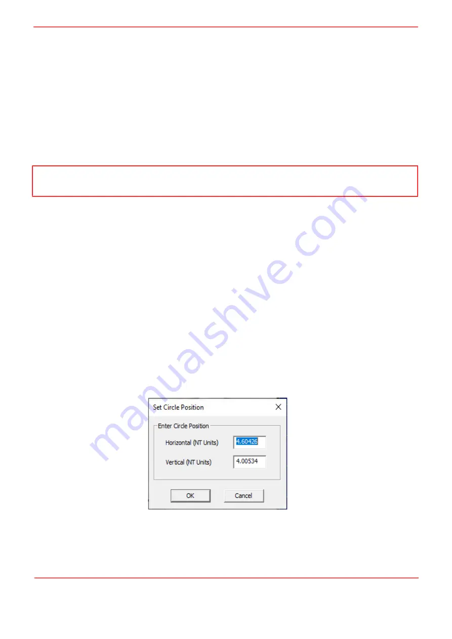
5.3 Circle Position Window
Right click in the Circle Position Display, to show the position window.
This window shows the current circle position in whatever display units are selected, NanoTrak units or Microns. The circle
can be positioned by entering a value into the X and/or Y fields and clicking the arrow.
Note
If the circle diameter adjustment mode is set to 'Auto', the actual circle diameter may be different to the diameter displayed
in the Settings window. (see Section C.1.3. for further information).
Summary of Contents for NanoTrak KNA-IR
Page 47: ...www thorlabs com ...


