Rev B Sept 2020
Page 17
Chapter 4 Standalone Operation
4.2.7 Menu Option - 7 SIGNAL OUT
The internal piezo drivers of the KNA unit are limited to an output current of around 5 mA, which is insufficient for some of the
higher circle scanning frequencies available. In this case it will be necessary to route the output signals from the NanoTrak K-
Cube to an external piezo driver that has a higher operating bandwidth. This option allows the NanoTrak cube to be used with
external piezo drivers, whereby the I/O 2 connector on the front panel can be configured as an external output. and the power
signal is output as a 0 to 2 V signal via this SMA connector.
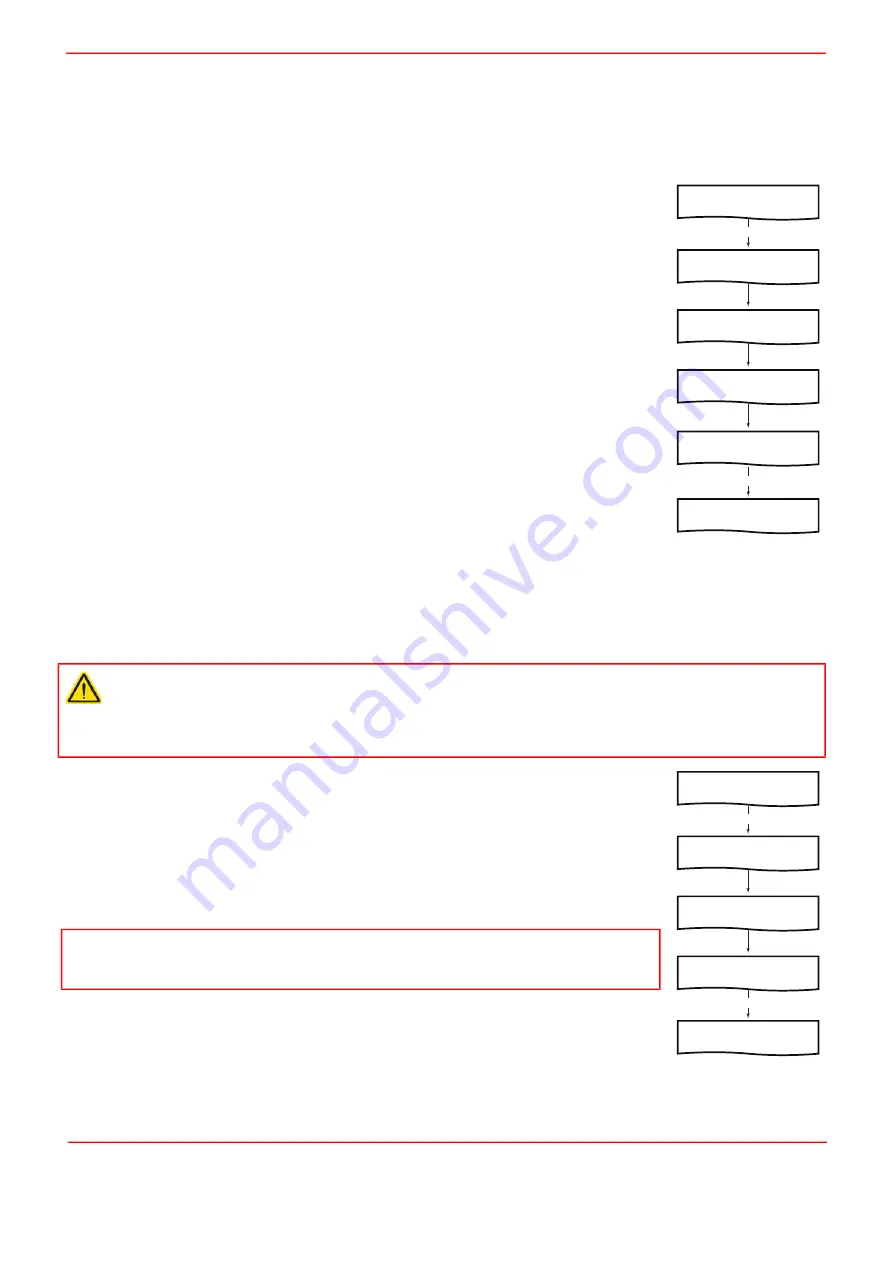
Press the MENU button, then use the wheel to scroll through the menu options
Press the MENU button to enter the 7 SIGNAL OUT option.
Use the wheel to select OFF or I/O 2 as required.
Press MENU to save the setting.
4.2.8 Menu Option - 8 OUTPUTS LATCH
When the maximum power has been located, the unit is usually switched to latch mode to hold the position. However, due to
environmental temperature and other factors, the piezos can drift over time. This menu option allows a FEEDBACK mode to
be selected, whereby a feedback loop is employed. Any drift from the desired position is corrected and the maximum power
position maintained.
This option is used to set the latch mode for both output channels.
Press the MENU button, then use the wheel to scroll through the menu options
Press the MENU button to enter the 8 OUTPUTS LATCH option.
Use the wheel to select either NORMAL or FEEDBACK as required.
Press MENU to save the setting.
Caution
FEEDBACK operation is only possible if an external position reader (such as the KSG101 Strain Gauge Reader) is used
in conjunction with the KNA unit. If the KNA unit is switched to FEEDBACK mode without being connected to a Strain
Gauge Reader, the unit will expect a feedback signal and the piezo drive voltage will ramp up to the maximum limit, either
75 V or 150 V, whichever is selected in the Input/Output tab.
Note
Using the APT software, the latch mode can be set to different values for each HV OUT connector
and in this case, the display will show LATCH: SW MIXED, see Section 5.4.2. for more details.
O P T I O N M E N U
U s e m e n u & w h e e l
7 S I G N A L O U T
P r e s s m e n u t o . . .
S I G N O U T : O F F
U s e t h e w h e e l . . .
S I G N O U T : I / O 2
U s e t h e w h e e l . . .
MENU
MENU
T r a c k i n g H E L D
1 : 5 0 . 0 % 2 : 4 9 . 1 %
T r a c k i n g H E L D
1 : 6 0 . 0 % 2 : 4 9 . 1 %
O P T I O N M E N U
U s e m e n u & w h e e l
8 O U T P U T S L A T C H
P r e s s m e n u t o . . .
L A T C H : N O R M A L
U s e t h e w h e e l . . .
MENU
MENU
T r a c k i n g H E L D
1 : 5 0 . 0 % 2 : 4 9 . 1 %
T r a c k i n g H E L D
1 : 6 0 . 0 % 2 : 4 9 . 1 %
Summary of Contents for NanoTrak KNA-IR
Page 47: ...www thorlabs com ...


