Rev B Sept 2020
Page 33
Chapter 5 PC Operation - Tutorial
7) In the slave NanoTrak GUI, select ‘Settings’.
8) Select the ‘Tracking’ tab, then set the Circle User Frequency, e.g. 30 Hz.
9) Select the ‘Input/Output’ tab, then set the Input Signal Source to ‘2 V SMA’.
10)Set both NanoTraks to ‘Track’.
11)Once alignment is achieved, tracking can be verified. Move the axes of the stage(s) by a small amount. The circle of the
NanoTrak associated with the stage should move accordingly to follow the signal.
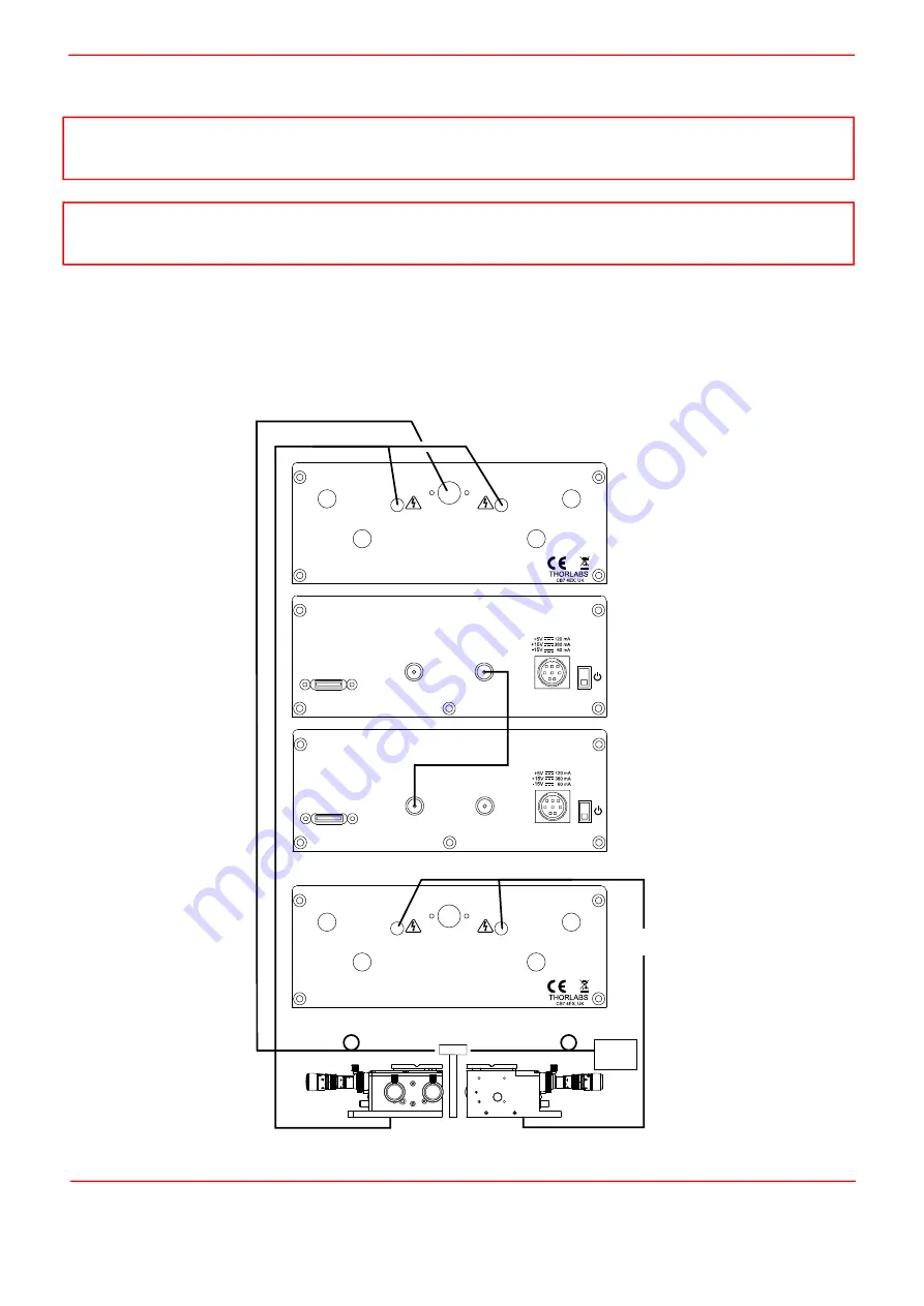
If using the internal power meter, the detector output is connected to the OPTICAL INPUT connector on the master unit and
the signal to the slave NanoTrak must be routed from the master I/O 2 to the slave I/O 1. If using an external power meter, this
is connected to I/O 1 on the master unit.
Fig. 5.7 Dual NanoTrak connections
Note
A difference of at least 10 Hz is recommended between this frequency and that set at item (5). This is to ensure adequate
frequency separation between the bandpass filters of the two NanoTraks.
Note
With SMA input source selected, the internal TIA circuit is bypassed and therefore autoranging is not required. Also, the
Tracking Indicator on the GUI panel is inoperative.
laser
source
input fiber
output fiber
waveguide
O/P piezo drive connections
Optical Input
I/P piezo drive connections
MONITOR 1
OPTICAL INPUT
MONITOR 2
HV
OUT 1
0 - 150V
HV
OUT 2
0 - 150V
EXT
IN 1
0 - 10V
EXT
IN 2
0 - 10V
900 - 1700 nm 1.5 mW
MONITOR 1
OPTICAL INPUT
MONITOR 2
HV
OUT 1
0 - 150V
HV
OUT 2
0 - 150V
EXT
IN 1
0 - 10V
EXT
IN 2
0 - 10V
900 - 1700 nm 1.5 mW
KNA-IR
USB
I/O 1
I/O 2
+5V TTL
+5V TTL
ON
KNA-IR
USB
I/O 1
I/O 2
+5V TTL
+5V TTL
ON
Output NanoTrak
Rear Panel
Output NanoTrak
Front Panel
Intput NanoTrak
Front Panel
Intput NanoTrak
Rear Panel
Summary of Contents for NanoTrak KNA-IR
Page 47: ...www thorlabs com ...


