


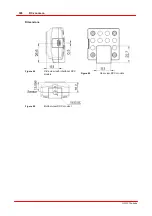
381
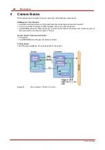
Camera Basics
© 2010 Thorlabs
9.13
Interface Basics
9.13.1
History and development
The Universal Serial Bus (USB) is an interface which allows easily connection of different devices to
a PC. All data transmission is controlled by the PC and no special interface controller is required.
Further advantages of USB are:
The system does not have to be shut down when connecting USB devices (hot plugging).
USB devices can be supplied with voltage from the PC.
The USB standard was developed by a consortium of companies like Compaq, IBM, Intel, Microsoft
and others. Version 1.0 was introduced in 1995, the slightly faster USB1.1 standard followed in
1998.
At first, the USB interface was designed to connect devices such as printers, mice and keyboards.
With the introduction of USB2.0 in 2001 the bus bandwidth increased to 480 MBit/s, making USB2.0
suitable for devices with high data rates (such as mass storage devices, scanners or cameras).
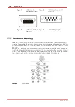
9.13.2
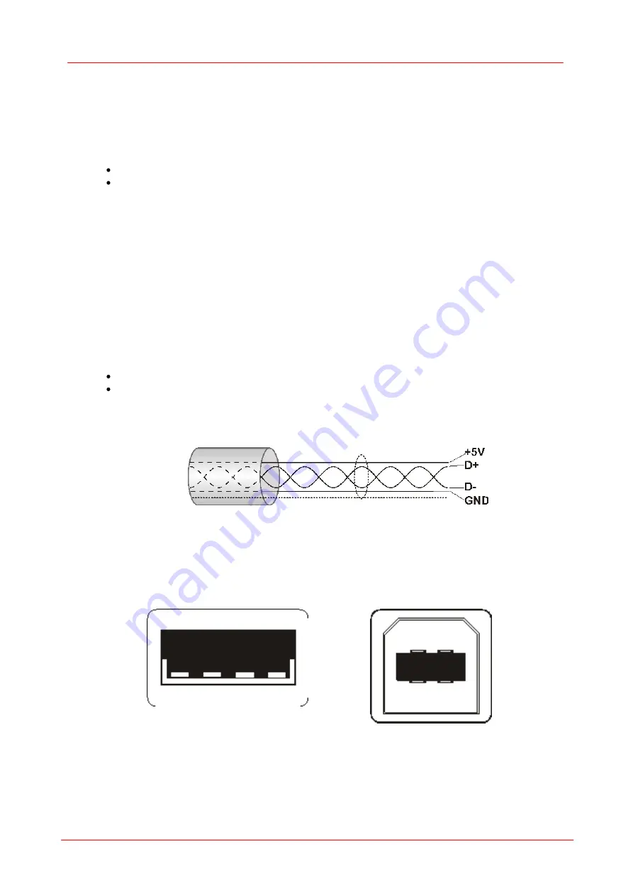
Cable and connection
The maximum length for USB2.0 cables is limited to 5m in order to comply with the specifications.
Longer cables are allowed if high quality material is used.
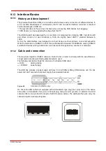
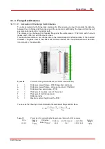
The following illustration shows the structure of a shielded USB cable:
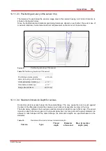
D+/D-:
data signalling
+5V/GND:
power supply
The USB bus provides a power supply with max. 5V and 500mA. Many USB devices use the bus
power and don’t need external power supply (bus-powered devices).
Figure 80
Structure of a USB of cab le
On host side USB cables are equipped with a Standard-A type plug (four pins) and on the device
side either a Standard-B (four pins) or Mini-B plug (five pins with ground). In addition the DCU
cameras offer a nine pin Sub-D connector for DCU camera cables. The additional four pins carry the
camera’s digital input/output signals.
Summary of Contents for DCC1 45 Series
Page 5: ...Version Date 3 5 2 22 09 2010 2010 Thorlabs 2010 Thorlabs ...
Page 13: ......
Page 15: ......
Page 16: ...Introduction DCx camera Part I ...
Page 18: ...General Information DCx camera Part II ...
Page 21: ......
Page 22: ...Getting Started DCx camera Part III ...
Page 24: ...Installation DCx camera Part IV ...
Page 30: ...uc480 Camera Manager DCx camera Part V ...
Page 38: ...Camera viewer uc480Viewer DCx camera Part VI ...
Page 45: ...40 DCx camera 2010 Thorlabs Menu Help Figure 15 Info about Camera viewer uc480Viewer ...
Page 87: ......
Page 88: ...SDK Software development Kit DCx camera Part VII ...
Page 109: ...104 DCx camera 2010 Thorlabs Figure 52 Flowchart Handling events messages ...
Page 121: ...116 DCx camera 2010 Thorlabs Flowchart Digital output Figure 57 Flowchart Digital output ...
Page 161: ...156 DCx camera 2010 Thorlabs Related Functions is_GetCameraType is_CameraStatus 159 121 ...
Page 175: ...170 DCx camera 2010 Thorlabs is_GetExposureTime 167 ...
Page 238: ...233 SDK Software development Kit 2010 Thorlabs is_SetImagePos is_SetPixelClock 271 277 ...
Page 261: ...256 DCx camera 2010 Thorlabs is_SetTriggerDelay 289 ...
Page 271: ...266 DCx camera 2010 Thorlabs is_SetGainBoost is_SetAutoParameter 261 221 ...
Page 283: ...278 DCx camera 2010 Thorlabs is_SetSubSampling is_SetAOI 284 219 ...
Page 291: ...286 DCx camera 2010 Thorlabs is_SetAOI is_SetImagePos is_SetPixelClock 219 271 277 ...
Page 361: ......
Page 362: ...Maintenance and Service DCx camera Part VIII ...
Page 370: ...365 Maintenance and Service 2010 Thorlabs ...
Page 371: ......
Page 372: ...Camera Basics DCx camera Part IX ...
Page 389: ......
Page 390: ...Appendices DCx camera Part X ...
Page 397: ...392 DCx camera 2010 Thorlabs Figure 90 Securing the adjusting ring ...
Page 405: ...400 DCx camera 2010 Thorlabs Figure 106 Rev 2 0 Flash Strobe output as Open Emitter OE ...
Page 420: ......


