


371
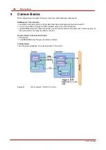
Camera Basics
© 2010 Thorlabs
also influence the bandwidth required for a camera.
The pixel clock influences the connected load and consequently the temperature
inside the camera.
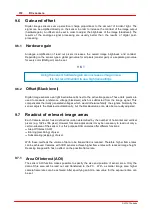
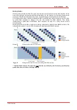
Frame rate
The possible range of settings for the frame rate depends on the currently selected pixel clock. You
can select a lower frame rate without changing the pixel clock. To set a higher frame rate, however,
you need to increase the pixel clock.
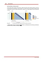
Exposure time
The exposure time depends on the currently selected frame rate and is preset to its reciprocal value.
You can select a shorter exposure time without changing the frame rate. To set a longer exposure
time, however, you need to reduce the frame rate.
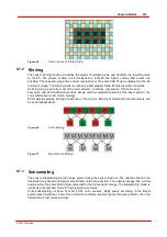
9.5
Image Display Modes
The
DCx
driver provides three different modes for the display of captured images: The device
independent Bitmap mode (DIB), DirectDraw BackBuffer mode and DirectDraw Overlay mode.
Device Independent Bitmap mode (DIB)
In Bitmap mode, images captured by the
DCx
are written to the random access memory of the
PC. The application software initiates the image display by the graphics card. This may result in a
slightly higher CPU load as compared to the DirectDraw display.
The advantage of Bitmap mode is that it is compatible with all graphics cards and that image data
in the memory is directly accessible. Since Windows controls the image display, the image may
be completely or partly overlapped by any other windows and dialog boxes.
DirectDraw BackBuffer mode
In this mode, the
DCx
driver writes the image data to the invisible memory area (back buffer) of the
graphics card. This process runs automatically and does not have to be controlled by the
application software. It requires an installed DirectDraw driver, sufficient memory on the graphics
card and back buffer function support by the graphics card.
For this purpose, graphics cards generally provide better performance than graphics chips
integrated on the mainboard. In DirectDraw mode, the CPU load may be lower than in Bitmap
mode.
DirectDraw Overlay Surface mode
This mode enables simultaneous display of a live image and overlay data. The video image is
digitized and stored in an invisible memory area (back buffer) of the graphics card. Defining a key
color and drawing that color to the image output window results in the video image being displayed
in all areas of the output window that have this key color. If the key color fills the entire window,
the video image is displayed full-screen. Accordingly, graphics/text data is preserved in all areas
not filled with the key color. This produces a non-destructive overlay. The display is controlled by
the graphics card chip and therefore hardly requires any CPU time. This mode is not supported by
all graphics cards, and often, it can only be used in conjunction with the YUV color mode.
Summary of Contents for DCC1 45 Series
Page 5: ...Version Date 3 5 2 22 09 2010 2010 Thorlabs 2010 Thorlabs ...
Page 13: ......
Page 15: ......
Page 16: ...Introduction DCx camera Part I ...
Page 18: ...General Information DCx camera Part II ...
Page 21: ......
Page 22: ...Getting Started DCx camera Part III ...
Page 24: ...Installation DCx camera Part IV ...
Page 30: ...uc480 Camera Manager DCx camera Part V ...
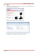
Page 38: ...Camera viewer uc480Viewer DCx camera Part VI ...
Page 45: ...40 DCx camera 2010 Thorlabs Menu Help Figure 15 Info about Camera viewer uc480Viewer ...
Page 87: ......
Page 88: ...SDK Software development Kit DCx camera Part VII ...
Page 109: ...104 DCx camera 2010 Thorlabs Figure 52 Flowchart Handling events messages ...
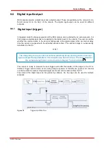
Page 121: ...116 DCx camera 2010 Thorlabs Flowchart Digital output Figure 57 Flowchart Digital output ...
Page 161: ...156 DCx camera 2010 Thorlabs Related Functions is_GetCameraType is_CameraStatus 159 121 ...
Page 175: ...170 DCx camera 2010 Thorlabs is_GetExposureTime 167 ...
Page 238: ...233 SDK Software development Kit 2010 Thorlabs is_SetImagePos is_SetPixelClock 271 277 ...
Page 261: ...256 DCx camera 2010 Thorlabs is_SetTriggerDelay 289 ...
Page 271: ...266 DCx camera 2010 Thorlabs is_SetGainBoost is_SetAutoParameter 261 221 ...
Page 283: ...278 DCx camera 2010 Thorlabs is_SetSubSampling is_SetAOI 284 219 ...
Page 291: ...286 DCx camera 2010 Thorlabs is_SetAOI is_SetImagePos is_SetPixelClock 219 271 277 ...
Page 361: ......
Page 362: ...Maintenance and Service DCx camera Part VIII ...
Page 370: ...365 Maintenance and Service 2010 Thorlabs ...
Page 371: ......
Page 372: ...Camera Basics DCx camera Part IX ...
Page 389: ......
Page 390: ...Appendices DCx camera Part X ...
Page 397: ...392 DCx camera 2010 Thorlabs Figure 90 Securing the adjusting ring ...
Page 405: ...400 DCx camera 2010 Thorlabs Figure 106 Rev 2 0 Flash Strobe output as Open Emitter OE ...
Page 420: ......


