background image

MEC 310 GENSET CONTROLLER


PM075 REV 2  09/08/20   


Page 59  


THOMSON TECHNOLOGY 


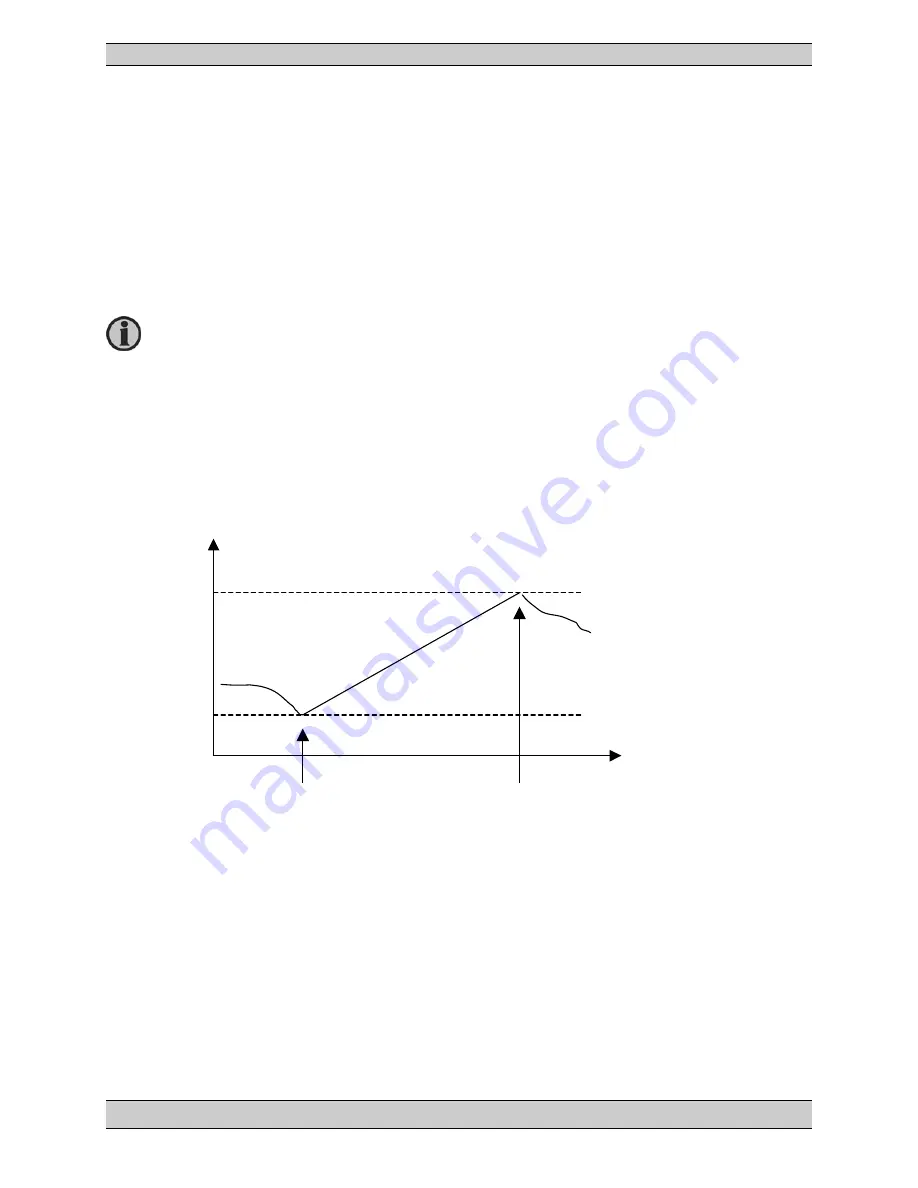
Fuel pump logic 

 
The fuel pump logic is used in order to start and stop the fuel supply pump to maintain the fuel level in 
the service tank at predefined levels. The start and stop limits are detected from the VDO 1 input. 
 

Start level, factory setting at 20% 6551 
Stop level, factory setting at 80% 6552


• 

Start level, relay 2 activates 

• 

Stop level, relay 2 deactivates 


Fuel pump start level 

Fuel level 

80% 

20% 

Time 

Fuel service tank level 

Fuel pump stop level 

The fuel pump relay is an NO relay and is configured to relay 2 by default. This 
configuration cannot be changed. If other alarm functions have been configured 
to  relay  2,  and  the  fuel  logic  is  activated,  then  a 

relay  channel  error

  alarm  will 

occur. Please make sure that relay 2 is configured to Fuel Pump. 

Summary of Contents for MEC 310 - APLLICATION NOTES EXTERNAL I-O MODULES

Page 1: ...et Langley BC Canada V1M 3B1 Telephone 604 888 0110 Fax 604 888 3381 E Mail info thomsontechnology com www thomsontechnology com MEC 310 GENSET CONTROLLER INSTALLATION AND OPERATION MANUAL r 0472f PM0...

Page 2: ...This description of options covers the following products MEC 310 SW version 1 2X X...

Page 3: ...ER ALTERNATOR CONNECTIONS 13 CONNECTION OF THE 3 PHASE VOLTAGE AND CURRENT 14 CONNECTION OF THE 1 PHASE 2 WIRE VOLTAGE AND CURRENT 14 CONNECTION OF THE 2 PHASE 3 WIRE VOLTAGE AND CURRENT 15 COMMUNICAT...

Page 4: ...MMUNICATION 74 SMS ALARMS 75 TPS 300 SOFTWARE CONNECTION VIA MODEM 76 TPS 300 SOFTWARE COMMUNICATION SAFETY 77 AUTO ENGINE START 78 START SEQUENCES 79 STOP SEQUENCES 84 5 PARAMETER LIST 86 PARAMETER G...

Page 5: ...he unit setup Naturally others might also find useful information in the handbook Contents overall structure The Installation Instructions and Reference Handbook is divided into chapters and in order...

Page 6: ...r deals with push button and LED functions Furthermore information about the display including icon list is presented Functional descriptions This chapter includes functional descriptions for the unit...

Page 7: ...onnected these precautions are no longer necessary Safety issues Installing the unit implies work with dangerous currents and voltages Therefore the installation should only be carried out by authoriz...

Page 8: ...LLER PM075 REV 2 09 08 20 Page 4 THOMSON TECHNOLOGY Warnings The warnings indicate a potentially dangerous situation which could result in death personal injury or damaged equipment if certain guideli...

Page 9: ...e it contains a full 3 phase AC voltage and current measuring circuit The unit is equipped with an LCD display presenting all values and alarms Standard functions Engine control Start preparation preh...

Page 10: ...ds Clear text display 128 x 64 pixel backlight STN Alarm texts editable All texts in multi language Clear text alarm messages Clear text diagnostics for both hardwired inputs and CANbus messages J1939...

Page 11: ...ttom of the MEC 310 box Terminals Unit rear view For Use on a Flat Surface of a Type 1 Enclosure The RJ11 connector for the PC connection interface SSP is placed on the side of the unit 1 2 3 4 5 6 7...

Page 12: ...coil configurable Function NO 24 25 Relay output 24 Contact ratings 8A 30V DC V AC UL C UL 6A Resistive Horn configurable Function NO 26 27 Relay output 26 Contact ratings 8A 30V DC V AC UL C UL 6A R...

Page 13: ...ptional CANbus engine interface option J 53 CAN H CAN J1939 engine communication 54 CAN GND 55 CAN L Optional CANbus port 2 External I O interface feature EXP 57 CAN H CAN communication port to Extern...

Page 14: ...can be configured to cover the following functions Magnetic pick up 2 wire NPN or PNP pick up These RPM inputs require external equipment Tacho RPM input with capacitor M L can be configured to cover...

Page 15: ...er STOP 1 2 F Battery Status 10 11 13 14 24 Alarm Horn R24 25 Starter Engine communication option Multi functional inputs Binary input w cable superv VDO sensors Multi functional inputs Can H Can L Co...

Page 16: ...ted configuration is the default factory setting The use of the relays can be chosen freely It is important to protect the unit against damage caused by high voltages Therefore the fuse must not be mo...

Page 17: ...cranking the battery will supply the D through the REX resistor helping the alternator to excite When the alternator starts to produce voltage excitation OK the speed of the alternator will be above r...

Page 18: ...S1 N L1 U L1 33 36 U L2 40 L1 s2 39 L1 s1 Generator voltages current Generator N L1 14 GB OFF feedback Supply Generator MEC 310 GB ON command 45 46 CONSUMER GB U L3 38 34 Neutral L2 L2 L3 L3 L2 s1 41...

Page 19: ...MEC 310 GENSET CONTROLLER PM075 REV 2 09 08 20 Page 15 THOMSON TECHNOLOGY Connection of the 2 phase 3 wire voltage and current...

Page 20: ...vice can be linked together using a third wire CANbus Termination resistor The size of the terminating resistors should be 120 1 0 5W resistor Option M Modbus RTU Connection with 3 wire shielded cable...

Page 21: ...ns in this section In case of very long lines on the network terminating resistors might be needed typically 120 1 0 5W The calculation should be based on the following data A line internal pull up bi...

Page 22: ...20 Page 18 THOMSON TECHNOLOGY Option J CANbus engine communication Connection with 2 wire shielded cable recommended Connection with 3 wire shielded cable For wiring details please refer to Wiring in...

Page 23: ...THOMSON TECHNOLOGY External I O modules For wiring details please refer to Wiring instructions in this section If External I O modules is used together with EAP 300 the total terminal resistance of t...

Page 24: ...Wiring instructions in this section If the External I O modules are used together with EAP 300 the total terminal resistance of the EAP 300 and the External I O controller must be 120 A DC DC convert...

Page 25: ...phase 20 Load 1 5M Measuring input current In 1A or 5A AC from current transformer Load Max 0 3VA per phase Frequency 30 70Hz Analogue input From active transducer Current 0 4 20mA Impedance 50 Wire b...

Page 26: ...00 6 1 2 3 4 SS4631503 PL4 and IEC 255 3 Material All plastic materials are self extinguishing according to UL94 Plug connections AC voltage inputs 3 5 mm 2 multi stranded 13 AWG Other 1 5 mm 2 multi...

Page 27: ...MEC 310 GENSET CONTROLLER PM075 REV 2 09 08 20 Page 23 THOMSON TECHNOLOGY Unit dimensions and panel cutout...

Page 28: ...running mode OFF Stops the engine immediately If the unit is in AUTO mode the mode will change to MAN and the engine will stop Breaker TRIP Breaker CLOSE AUTO running mode selector Enters value or ac...

Page 29: ...de selector MAN Manual running mode selector TEST Initiates the test sequence selected for the push button LAMP TEST Lamp test One push will illuminate all LEDs for 3 seconds ESC Jumps from parameter...

Page 30: ...s present Additional alarm indication LEDs Flashing red Active non acknowledged alarm s where output A or B is configured to LED 1 2 3 or 4 Steady red Active acknowledged alarm s where output A or B...

Page 31: ...h the list Exit the list by pressing ESC Press to enter the parameter setting Parameter example D delay setting Use or to scroll through the settings list If change of settings is necessary press and...

Page 32: ...present alarms and the alarm LED will change from flashing to steady light The display can be used in the alarm information window The alarm information window displays one alarm at a time and the al...

Page 33: ...parameters Configurable Start enable OFF start blocked Configurable GB Pos on Configurable GB Pos off Configurable MB Pos on Configurable option A MB Pos off Configurable option A Access lock Configu...

Page 34: ...the control push buttons on the display It will only be possible to view measurements alarms and the log 11 Mode shift Selection between manual and auto running The mode is changed every time the inpu...

Page 35: ...meter 6212 3 Prepare This function will close the relay as the first thing in the start sequence The relay will be closed for the time programmed in parameter 6181 This function is used for preheating...

Page 36: ...ameter 5000 to 5060 9 Fuel pump Output must be configured to use fuel pump settings 10 Engine heater The relay configured to Engine heater will close when the temperature is below the set point in par...

Page 37: ...e input is used as alarm input then the name can be changed to the relevant name selected from the predefined list below 3000 3050 Digital input term 10 15 without wire break detection Complete the in...

Page 38: ...set is running the inhibit settings must be used If etc Not run status is ticked in the inhibit settings it means that the alarm is inhibited until the running feedback is present when the Run status...

Page 39: ...on Shutdown relay output you would need to perform the following steps NOTE For this example Relay 45 will be used as a Common Shutdown and Relay 47 will be used as a Common Alarm 1 In the I O Setting...

Page 40: ...n list found in the Setpoint section select Limit function 3 Under the M Logic tab the user will need to setup a Logic rung for Common Warning and a Logic rung for Common Shutdown Have each Logic rung...

Page 41: ...lowing information for Relay 47 Common Alarm NOT Event A Warning Failclass Output Relay 47 Relays Enable this rule From the dropdown list for Event A Select Shutdown From the dropdown list for Output...

Page 42: ...he user will need to setup all of the required Channels that will need to be associated to the Common Alarm or Common Shutdown relays Example Parameter Settings Setup parameter with required Setpoints...

Page 43: ...alarm has been made The inhibit functionality is only available via the PC utility software For every alarm there is a drop down window where it is possible to select which signals that have to be pre...

Page 44: ...60 expired Not run status Running not detected or the timer in menu 6160 not expired Generator voltage 30 Generator voltage is above 30 of nominal Generator voltage 30 Generator voltage is below 30 of...

Page 45: ...310 GENSET CONTROLLER PM075 REV 2 09 08 20 Page 41 THOMSON TECHNOLOGY Configuration of the External I O External I O s have the same popup window with parameter settings as the internal I O s in MEC...

Page 46: ...al I O s are done the same way as the inbuilt I O s in MEC 310 Using TPS 300 software Only available external I O s are listed in Input Output view If e g one hardware module is removed it will also b...

Page 47: ...template on the cd rom Configuration of the alarm indication LEDs The alarm indication is able to indicate alarm status on one single alarm or a group of alarms The factory setting for the LEDs is not...

Page 48: ...ty to display different languages It is delivered with one master language which is English furthermore three languages which are selected by the customer on the order specification One or all of the...

Page 49: ...own in the display Parameter texts used in the PC USW will only be shown in master language Icons used for upload download of translation Setup for characters Sync icon used to synchronise between mas...

Page 50: ...start Open gen breaker Stop generator Cooldown Shutdown 0 Warning X X 1 Trip of GB X X X 2 Trip and stop X X x X X X 3 Shutdown X X x X X X When alarm horn relay output is selected active Fail class c...

Page 51: ...whenever the amount of days or the amount of running hours has expired If the service timer is set to count down the display will shown 0 days or 0 hours if the service timer is set to count up the di...

Page 52: ...s Counting at each GB close command 6105 kWh reset Resets the kWh counter Automatically resets to OFF after the reset The reset function cannot be left active Command timer The purpose of command time...

Page 53: ...08 20 Page 49 THOMSON TECHNOLOGY Hour setting Minute setting The digital input auto start stop cannot be used when this function is enabled It is necessary to use the TPS 300 software when setting up...

Page 54: ...N G L2 N XXX V G L3 N G L3 N XXX V G I L1 G I L1 XXX A G I L2 G I L2 XXX A G I L3 G I L3 XXX A G P L1 G P L1 XXX kW G P L2 G P L2 XXX kW G P L3 G P L3 XXX kW G f L1 G f L1 XX X Hz G L1 L2 L3 G L1 L2 L...

Page 55: ...EIC T Coolant EIC L Coolant EIC L Coolant EIC P Coolant EIC P Coolant EIC T Oil EIC T Oil EIC L Oil EIC L Oil EIC P Oil EIC P Oil EIC T Fuel EIC T Fuel EIC P Fuel EIC P Fuel EIC T Air Inl EIC T Air In...

Page 56: ...ometric EIC T Ambient Air EIC T Ambient Air EIC T Exh Right EIC T Exh Right EIC T Exh Left EIC T Exh Left EIC T Winding 1 EIC T Winding 1 EIC T Winding 2 EIC T Winding 2 EIC T Winding 3 EIC T Winding...

Page 57: ...MEC 310 GENSET CONTROLLER PM075 REV 2 09 08 20 Page 53 THOMSON TECHNOLOGY 8 15 display views are empty...

Page 58: ...VDO sensor type Type 1 Value Resistance 0 78 8 100 1 6 VDO sensor type Type 2 Value Resistance 0 3 100 180 VDO sensor type Value Type 3 Resistance 0 Configurable 10 20 30 40 50 60 70 80 90 100 In the...

Page 59: ...i 0 0 10 0 10 0 Configurable 0 5 7 27 2 1 0 15 44 9 1 5 22 62 9 2 0 29 81 0 51 5 2 5 36 99 2 3 0 44 117 1 71 0 3 5 51 134 7 4 0 58 151 9 89 6 4 5 65 168 3 5 0 73 184 0 107 3 6 0 87 124 3 7 0 102 8 0 1...

Page 60: ...Type 1 Type 2 Type 3 Type 4 C F 40 104 291 5 480 7 69 3 Configurable 50 122 60 140 134 0 222 5 36 0 70 158 97 1 27 9 80 176 70 1 113 2 19 8 90 184 51 2 83 2 15 8 100 212 38 5 62 4 11 7 110 230 29 1 47...

Page 61: ...m settings in menus 4230 VDO fuel level input 2 1 4240 VDO fuel level input 2 2 VDO input 2 Lubricating oil pressure alarm settings in menus 4310 VDO oil pressure input 2 1 4320 VDO oil pressure input...

Page 62: ...i functional inputs the 3 VDO inputs can be changed to binary inputs with cable supervision The cable supervision is selectable ON OFF and based on the VDO inputs using a 100 Ohm resistor across the m...

Page 63: ...ry setting at 20 6551 Stop level factory setting at 80 6552 Start level relay 2 activates Stop level relay 2 deactivates Fuel pump start level Fuel level 80 20 Time Fuel service tank level Fuel pump s...

Page 64: ...uel level must increase with 4 within the fuel fill check timer This timer is adjusted in 6550 Fuel pump logic but the level of increase cannot be changed If the fuel level does not increase at least...

Page 65: ...0 4 20mA setting can only be set in the TPS 300 software 4 20mA inputs have wire break detection The wire break detection limit is 2 5mA Settings Scale top point value click the Alarm setpoint Freely...

Page 66: ...te Only one running feedback is needed but for optimal safety and function both the RPM Tacho input and the digital running feedback D can be used as in the example below Rex Excitation resistor 12V s...

Page 67: ...up Since the NPN output is a frequency modulated DC pulse signal a few external components are needed in order to eliminate the DC component R 1200 24V DC 600 12V DC PNP transistor output pick up Sinc...

Page 68: ...he input Breaker ON feedback is selected then the input must be connected and activated if the breaker is ON The reason is that a Breaker close failure alarm will appear if the breaker control relay i...

Page 69: ...the option A is enabled The test sequences can be initiated in two ways Either with the test push button on the front of the MEC 310 or by a digital input configured to this function Simple test funct...

Page 70: ...this sequence should be started by a digital input and or the test push button on the front of the MEC 310 If the timer is set to 0 the test sequence will be interrupted when the digital input or tes...

Page 71: ...onditions are defined and at the activation of those inputs the defined output will occur A great variety of inputs can be selected such as digital inputs alarm conditions and running conditions A var...

Page 72: ...rn annunciator the input must be set to Horn and the output must be set to Buzzer The buzzer will act concurrently to the horn output timer If the delay timer in M logic is used the buzzer will be act...

Page 73: ...REV 2 09 08 20 Page 69 THOMSON TECHNOLOGY Upgrade of firmware 1 Connect PC to MEC 310 using Thomson Technology SSP interface 2 Open TPS 300 software USW and connect to MEC 310 3 Read parameters from M...

Page 74: ...MEC 310 GENSET CONTROLLER PM075 REV 2 09 08 20 Page 70 THOMSON TECHNOLOGY 4 Select ALL parameters to be saved in USW project file 5 Choose file name and where to save project file on PC...

Page 75: ...79 file New application software can be downloaded from www thomsontechnology com 7 This will force MEC 310 into boot mode LED 1 will flash red If the programming should be interrupted it s possible t...

Page 76: ...age 72 THOMSON TECHNOLOGY 8 After download of new firmware is done saved parameters can be downloaded into unit 9 Open saved project file from PC 10 Write to device using Batch job function Indication...

Page 77: ...MEC 310 GENSET CONTROLLER PM075 REV 2 09 08 20 Page 73 THOMSON TECHNOLOGY 11 Select parameters which want to be downloaded into the unit 12 Restart unit...

Page 78: ...onnector on the modem side We recommend using Siemens MC35 modem The easiest way to get the modem is to purchase it through a local dealer The SIM card needed comes from your local mobile net provider...

Page 79: ...1 Setup GSM pin code 2 Setup of Alarm call numbers 3 Connect GSM modem to service port 4 Disconnect Aux supply to MEC 310 5 Connect Aux supply to MEC 310 6 MEC 310 will then setup the GSM modem under...

Page 80: ...and key in the telephone number of your GSM modem connected to the unit When you want to use modem dial up the TPS 300 software must also be set to run ASCII 7 bits data communication If a TPS 300 sof...

Page 81: ...tion fails the MEC 310 unit will operate according to the received data If e g only half of the parameter file has been downloaded when the communication is interrupted the settings are going to be a...

Page 82: ...ine start The mains fail is an option Start Auto Initiate start sequence No Yes Different mode Remote start input Yes No Mains fail Yes No f U timer expired No Yes Engine running No Yes Start sequence...

Page 83: ...N TECHNOLOGY Start sequences Start sequence Stop coil normal prepare Start prepare Start output Running feedback Stop output Start attempts Start sequence Run coil normal prepare Start prepare Start o...

Page 84: ...OMSON TECHNOLOGY Start sequence Run coil extended prepare Start prepare Start output Running feedback Run coil Start attempts 1 2 tOFF tOFF Start sequence Stop coil extended prepare Start prepare Star...

Page 85: ...TROLLER PM075 REV 2 09 08 20 Page 81 THOMSON TECHNOLOGY Start sequence Stop coil not acc in start seq normal prepare no stop between start attempts Start prepare Start output Running feedback Stop out...

Page 86: ...e the HORN output and relay outputs if selected Start prepare There are two possibilities for use of the start prepare timer Event Comment Auto mode stop Removal of start cause binary input or shutdow...

Page 87: ...auto only Select AUTO In both cases a relay must be selected to Idle in the output list When idle mode is selected a delay where the engine is running at low RPM is given The delay is controlled by t...

Page 88: ...top sequences The illustrations indicate the stop sequence schematically Cool dow n time Run coil Running feedback Stop sequence RUN coil tCOOL Cool dow n time Stop coil Running feedback Stop sequence...

Page 89: ...ns Stop command M logic X The stop sequence can only be interrupted during the cool down period Interruptions can occur in these situations Event Comment Start button is pressed Manual mode only Engin...

Page 90: ...enabled The default display parameter setting is the parameter setting that will always be present in the display parameter list These parameters are marked with a Setup The setup of parameters is per...

Page 91: ...one R26 relay 26 R0 none 4314 Oil pressure 2 1 Output B R0 none R26 relay 26 R0 none 4315 Oil pressure 2 1 Enable OFF ON OFF 4316 Oil pressure 2 1 Fail class Warning Shutdown Trip of GB The first colu...

Page 92: ...elay Setpoint 4120 4390 mA input settings 1460 Overload 2 Delay Setpoint 4310 4470 VDO multi input settings Parameter group 3 Disp view settings 4510 Gen overspeed 1 4220 Fuel 1 1 Delay Setpoint 4520...

Page 93: ...only configurable from USW 10010 Cmd 1 Days S 6700 Diode compensation 10020 Cmd 1 Hour S 6940 Alarm LED function 10030 Cmd 1 Minute S 6950 Parameter group 1 10040 10310 Cmd 2 Cmd 8 6960 Parameter gro...

Page 94: ...tions Fail class When the alarm occurs the unit will react depending on the selected fail class Fail class The fail class settings for the protections have the following possibilities Value Comment 0...

Page 95: ...setting Third setting Factory setting 1041 Overcurrent 2 P2 Set point 50 0 200 0 120 0 1042 Overcurrent 2 P2 Timer 0 1 s 3200 0 s 5 0 s 1043 Overcurrent 2 Relay output A R0 none R26 relay 26 R0 none 1...

Page 96: ...setting 1211 Overfrequency P2 Set point 80 0 150 0 115 0 1212 Overfrequency P2 Timer 0 1 s 100 0 s 10 0 s 1213 Overfrequency Relay output A R0 none R26 relay 26 R0 none 1214 Overfrequency Relay output...

Page 97: ...Overload 1 Fail class Warning Shutdown Warning 1460 Gen overload 2 No Setting Min setting Max setting Third setting Factory setting 1461 Overload 2 P2 Set point 10 0 200 0 110 0 1462 Overload 2 P2 Ti...

Page 98: ...ig input no XX Enable OFF ON Inhibit OFF 30X5 Dig input no XX Fail class See description of fail classes 30X6 Dig input no XX NO NC NO NC NO 3490 Emergency stop terminal 19 20 No Setting Min setting M...

Page 99: ...Setting Min setting Max setting Factory setting 3411 Binary input 2 Wire break OFF ON OFF 3412 Binary input 2 Delay 0 0 s 100 0 s 5 0 s 3413 Binary input 2 Output A R0 none R26 relay 26 R0 none 3414 B...

Page 100: ...0 none R26 relay 26 R0 none 4135 0 4 20mA 1 2 Enable OFF ON OFF 4136 0 4 20mA 1 2 Fail class See description of fail classes 4250 0 20 4 20mA 2 1 No Setting Min setting Max setting Factory setting 425...

Page 101: ...1 Output B R0 none R26 relay 26 R0 none 4385 0 4 20mA 3 1 Enable OFF ON OFF 4386 0 4 20mA 3 1 Fail class See description of fail classes 4390 0 20 4 20mA 3 2 No Setting Min setting Max setting Factory...

Page 102: ...4310 VDO oil press input 2 1 No Setting D Min setting Max setting Factory setting 4311 VDO 2 1 Set point 0 0 bar 10 0 bar 4 0 bar 4312 VDO 2 1 Delay 0 0 s 100 0 s 5 0 s 4313 VDO 2 1 Output A R0 none R...

Page 103: ...R0 none R26 relay 26 R0 none 4475 VDO 3 2 Enable OFF ON OFF 4476 VDO 3 2 Fail class See description of fail classes 4630 VDO low coolant temp input 3 3 No Setting Min setting Max setting Factory sett...

Page 104: ...2 Fail class See description of fail classes 4560 Hz V failure No Setting Min setting Max setting Factory setting 4561 Hz V failure Timer 1 0 s 99 0 s 30 0 s 4562 Hz V failure Relay output A R0 none...

Page 105: ...0 s 5 0 s 4623 Fuel level 1 3 Output A R0 none R26 relay 26 R0 none 4624 Fuel level 1 3 Output B R0 none R26 relay 26 R0 none 4625 Fuel level 1 3 Enable OFF ON OFF 4626 Fuel level 1 3 Fail class See d...

Page 106: ...OFF ON ON 4970 Battery high voltage No Setting Min setting Max setting Factory setting 4971 Battery high V Set point 15 0V 40 0V 28 0V 4972 Battery high V Timer 0 0 s 10 0 s 1 0 s 4973 Battery high V...

Page 107: ...25000V 400V 6005 Nominal settings 1 Nom RPM 1 0 RPM 4000 RPM 1500 RPM 6006 Nominal settings Set 6010 Nominal settings 2 No Setting Min setting Max setting Factory setting 6011 Nominal settings 2 Frequ...

Page 108: ...0V 480V 440V 6043 Transformer gen Current prim 5A 9000A 1000A 6045 Transformer gen Current sec 1A 5A 5A 6070 Gen set mode No Setting Min setting Max setting Factory setting 6071 Gen set mode Setpoint...

Page 109: ...21 Service timer 2 Type OFF Counting down Counting up OFF 6122 Service timer 2 Set point hours 1 10000 150 6123 Service timer 2 Set point days 1 1000 365 6124 Service timer 2 Fail class See descriptio...

Page 110: ...0 s 99 0 s 5 0 s 6190 Start attempts No Setting Min setting Max setting Factory setting 6191 Start attempts Attempts 1 10 3 6192 Start attempts Relay output A R0 none R26 relay 26 R0 none 6193 Start...

Page 111: ...e mode Timer 1 0 s 300 0 s 5 0 s 6293 Idle mode Active Man Man aut Aut Idle mode can be controlled via a binary input If this is selected the idle mode remains for as long as the input is ON If a bina...

Page 112: ...tting Min setting Max setting Factory setting 6561 Cool down timeout Timer 0 0 s 9999 0 s 900 0 s 6562 Cool down timeout Relay output A R0 none R26 relay 26 R0 none 6563 Cool down timeout Relay output...

Page 113: ...600 sec 6982 Sleep ON OFF OFF ON OFF The sleep mode is a standstill power save mode If the engine is stopped and nothing has happened within the time setting the unit will enter sleep mode i e the mo...

Page 114: ...ror Relay output B Not used Option dependent Not used 7574 EI comm error Enable OFF ON OFF 7575 EI comm error Fail class Unit dependent Warning No Setting Min setting Max setting Factory setting 7561...

Page 115: ...verspeed Delay 0 0 s 100 0 s 2 0 s 7603 EIC overspeed Relay output A Not used Not used 7604 EIC overspeed Relay output B Not used Option dependent Not used 7605 EIC overspeed Enable OFF ON OFF 7606 EI...

Page 116: ...Enable OFF ON OFF 7646 EIC oil press 2 Fail class Unit dependent Warning 7650 EIC oil Temp 1 No Setting Min setting Max setting Factory setting 7651 EIC oil temp 1 Set point 0 C 300 C 40 C 7652 EIC oi...

Page 117: ...setting Factory setting 10030 Cmd 1 min 0 59 0 10320 10370 GSM pin code and dial up numbers No Setting Min setting Max setting Factory setting 10320 GSM GSM pin code 0 9999 0 10331 GSM SMS telephone...

Page 118: ...hm 100 ohm 10620 VDO 1 Fuel level Output 8 0 150 120 10630 10790 Oil pressure config sensor No Setting Min setting Max setting Factory setting 10630 Oil pressure type Type 1 4 1 10640 VDO 2 Oil pressu...

Page 119: ...ohm 2500 ohm 90 ohm 10900 VDO 3 Water temp Output 5 0 150 90 C 10910 VDO 3 Water temp Input 6 0 ohm 2500 ohm 100 ohm 10920 VDO 3 Water temp Output 6 0 150 100 C 10930 VDO 3 Water temp Input 7 0 ohm 25...

Reviews: