


© 2000 ParkerVision, Inc. • Meet Your Student Camera System
Page 5
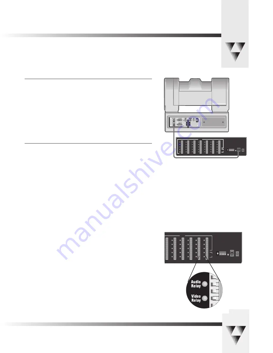
Mounting And Connecting The PRM
Connecting the PRM to the CameraMan
Using a 4-conductor cable, wired in a “straight-through” mode and terminated with
modular handset connectors, connect the RS-485 port on the back of the PRM to the
RS-485 port on the back of the CameraMan Camera.
Connecting the Contact Closure Outputs
The PRM’s AUDIO RELAY and VIDEO RELAY contact closure outputs are activated when a
“press-to-talk” microphone button is pressed, and deactivated when the button is pressed
again.
AUDIO RELAY
The intended application of this relay is to activate the mute switch of the audio system in the
room to prevent feedback when the microphone is active. The relay activates and the contacts
close only when a microphone button is pressed. In a typical application, the Audio Relay
contact closure would connect to an amplifier or audio switcher.
VIDEO RELAY
The intended application of this relay is to activate a video switcher to select between various
video sources. The relay activates and the contacts close only when a microphone button is
pressed. When the contact relay is closed, there is a two second delay to allow time for camera
movement before the video is switched. In a typical application, the Video Relay contact closure
would connect to a video switcher.
To Connect the Audio, or Video Relay:
1. Connect one end of a 2-conductor cable to the green connector block:
• Strip a short section (approximately 0.15”) off the end of the wire
• Insert the wire into the AUDIO RELAY or VIDEO RELAY screw terminal slot
on the connector block to the far right (the positive “+” lead is on top, the
negative “-” lead is on the bottom).
• Tighten the terminal screw
2. Connect the other end of the cable to your audio equipment per their instructions.
INPUTS
OUTPUTS
RS 485
DC
POW ER
1
2
3
4
5
6
7
8
9
10
11
12
13
14
15
16
17
18
19
20
21
22
23
24
25
26
27
28
29
30
31
32
33
Audio
Relay
Video
Relay
0
1
23
4 5 67
8
9
A
BC
DE
F
1 2 3 4 5 6 7 8
BASE
UNIT
ADDRESS
>8
>
> >
>
>
> 7
>6
>5
>4
>3
>2
>1
S
E
T
=
D
O
W
N
/
N
O
R
E
TU
R
N
=
U
P
}
R
E
TU
R
N
T
IM
E
S
E
TT
IN
G
(S
E
E
B
E
LO
W
)
N
O
R
M
A
L
=
D
O
W
N
/
A
U
D
IO
=
U
P
0 = DOWN/DOWN
5 SEC = UP/DOWN
10 SEC = DOWN/UP
15 SEC = UP/UP
{
>
I
N
P
U
T
32
N
O
R
M
A
L
=
D
O
W
N
/
O
P
TI
O
N
=
U
P
I
N
P
U
T
33
IN
P
U
T
33
O
P
TI
O
N
O
V
E
R
R
ID
E
=
D
O
W
N
/
A
U
D
IO
=
U
P
B
A
U
D
R
A
TE
96
00
=
D
O
W
N
/
19
20
0
=
U
P
N
O
T
U
S
E
D
PRM connected to CameraMan via RS-485 cable
INPUTS
OUTPUTS
RS 485
DC
POWER
1
2
3
4
5
6
7
8
9
10
11
12
13
14
15
16
17
18
19
20
21
22
23
24
25
26
27
28
29
30
31
32
33
Audio
Relay
Video
Relay
0
1
23
4567
8
9
A
BCD
EF
1 2 3 4 5 6 7 8
BASE
UNIT
ADDRESS
>
8
>
> >
>
>
>
7
>
6
>
5
>
4
>
3
>
2
>
1
SET = DOWN / NO RETURN = UP
}
RETURN TIME SETTIN
G
(SEE BELOW)
NORMAL
= DOWN
/
AUDIO = UP
0 = DOWN/DOWN
5 SEC = UP/DOWN
10 SEC = DOWN/UP
15 SEC = UP/UP
{
>
INPUT 32
NORMAL
= DOWN / OPTION = UP
INPUT 33
IN
P
U
T
3
3
O
P
T
IO
N
OVERRIDE = DOWN
/
AUDIO = UP
BAUD RA
TE
9600 = DOWN / 19200 = UP NOT USED
PRM Audio and Video
Relay Outputs


