THOMSON Grass Valley ParkerVision CameraMan Installation And Operation Manual Download Page 13

Page 10

CameraMan® 1-CCD and 3-CCD Student Camera System Installation and Operations Manual  •  © 2000 ParkerVision, Inc.

Problem:                The Camera’s Video is not working properly.

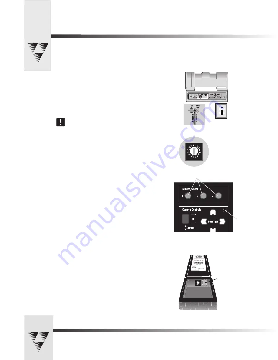
Solution:                  1.  Verify that the VIDEO SELECT switch on the back of the Camera is set

   properly, either S-VIDEO or COMPOSITE. 

2.   Verify that the appropriate video connection is being used on the 

back of the camera, either S-VIDEO or COMPOSITE VIDEO OUT. This is 

determined by the VIDEO SELECT Switch.


Only one video source can be utilized at any one time.  

Composite and S-Video formats cannot be used simultaneously.

Problem:                The Camera Control Keypad will not control the CameraMan Camera 

when used in the wireless RF mode.

Solution:                  1.  Verify that the battery is installed in the keypad properly. 

2.   Verify that the BASE UNIT ADDRESS switch on the back  of the 

CameraMan Camera, and the BASE UNIT ADDRESS switch in the battery 

compartment of the keypad and on the PRM are set to the same 

setting.

3.   Verify the RF command switch on the back of the CameraMan Camera 

is set to ENABLE.  (B4 needs to be in the DOWN position).

4.   Verify that the LED on the front of the Camera Control Keypad 

illuminates for a few seconds when the battery is first plugged in.

5.   Be sure that you have pressed the appropriate CAMERA SELECT button 

on the Keypad corresponding to the camera you wish to control. 


                               If only using one camera be sure to press CAMERA SELECT button 1.

Problem:                The Camera Control Keypad will not communicate with the 

CameraMan Student Camera in the “hard-wired” mode.

Solution:                  1.  Verify that the CameraMan Keypad Cable is connected from the PVI

  COM port on the back of the camera to the RJ-11 jack in the battery

  compartment of the Keypad.

2.   Does the light on the front of the keypad come on for a few seconds 

when the keypad is first plugged in? If not, replace cable with a 

ParkerVision supplied cable only. 

3.   Be sure that you have pressed the appropriate CAMERA SELECT button 

on the Keypad corresponding to the camera you wish to control. 

                               If only using one camera be sure to press CAMERA SELECT button 1.

Appendix A:  Troubleshooting

Should you have any problems with your CameraMan Student Camera System, please refer to the following guide. After referring 

to the guide, should you have any questions or problems, please contact your authorized reseller, or contact ParkerVision at 

(800) 532-8034 or (904) 737-1367.

Camera Select Buttons

Video Select 

Switch

Video 

connection 

jacks

Verify that the Base Unit 

Address Assignment 

Rotary Switch setting is 

the same on 

CameraMan Base Unit, 

Keypad, and PRM.

Communication LED

RJ-11 Jack

Summary of Contents for Grass Valley ParkerVision CameraMan

Page 1: ...1 CCD and 3 CCD Student Camera System Installation and Operations Manual L1209101 rev A FEBRUARY 2005...

Page 2: ...nloaded FAQ Database Solutions to problems and troubleshooting efforts can be found by searching our Frequently Asked Questions FAQ database Software Downloads Software updates drivers and patches can...

Page 3: ...eshooting 10 11 t A Specifications 11 t B Typical Student System Diagram 12 t C Warranty Information 13 The terms Visibly Better System II IMAGE WhisperDRIVE Plus and General Pan Tilt Camera System an...

Page 4: ...s it difficult for instructors at the far end to differentiate one student from the next and determine exactly which student is speaking With CameraMan each individual student can simply press the My...

Page 5: ...kground noise and cause unwanted camera motion The PRM works on a first come first served basis so when two or more students activate their microphones at the same time the first microphone activated...

Page 6: ...Switch t 16 position rotary switch used to tell the PRM which camera it controls It should match the Base Unit Address switch on the CameraMan camera The Factory Default is zero 0 DIP Switches t Used...

Page 7: ...tely 0 15 off the end of the wire 2 Insert the wire into the screw terminal slot on the connector plug 3 Tighten the terminal screw 4 Repeat steps 1 3 for the other 4 wire pairs in that connector bloc...

Page 8: ...act closure would connect to a video switcher To Connect the Audio or Video Relay 1 Connect one end of a 2 conductor cable to the green connector block Strip a short section approximately 0 15 off the...

Page 9: ...8 9 10 11 12 13 14 15 16 17 18 19 20 21 22 23 24 25 26 27 28 29 30 31 32 33 Audio Relay Video Relay 0 1 2 345 6 7 8 9 A B C D E F 1 2 3 4 5 6 7 8 BASE UNIT ADDRESS 8 7 6 5 4 3 2 1 SET DOWN NO RETURN...

Page 10: ...d for use by someone who wishes to be heard but does not want to cause the camera to position on them such as a room facilitator Configuring The Presets and Switches Diagram showing DIP Switch configu...

Page 11: ...the light does not illuminate the battery may be installed backwards Reverse the way the battery is inserted and try again If a low battery is installed the keypad will emit a long beep Note If the ba...

Page 12: ...e the manual ZOOM buttons to set the needed Zoom perspective 4 Only when desired use the manual IMAGE buttons to set the needed light dark contrast 5 Input the Location Preset number 1 33 that corresp...

Page 13: ...s first plugged in 5 Be sure that you have pressed the appropriate CAMERA SELECT button on the Keypad corresponding to the camera you wish to control If only using one camera be sure to press CAMERA S...

Page 14: ...positive and negative leads on the cable connecting that the microphones to the PRM are lined up correctly with the contact closure leads on the PRM Specifications KEYPAD RF CONTROL OPTION RF Range 6...

Page 15: ...ystem INPUTS OUTPUTS RS 4 85 DC POW ER 1 2 3 4 5 6 7 8 9 10 11 12 13 14 15 16 17 18 19 20 21 22 23 24 25 26 27 28 29 30 31 32 33 Audio Relay Video Relay 0 1 2 34 5 6 7 8 9 A B C D E F 1 2 3 4 5 6 7 8...

Page 16: ...nal product The warranty is non transferable Purchaser s failure to make a claim as provided above or continued use of the product shall constitute an unqualified acceptance of such product and a waiv...

Page 17: ...Page 14 CameraMan 1 CCD and 3 CCD Student Camera System Installation and Operations Manual 2000 ParkerVision Inc Notes...

Page 18: ...2000 ParkerVision Inc Literature Part Number L1209101 ref LPMCSC13 Revision D...

Reviews: