


© 2000 ParkerVision, Inc. • Meet Your Student Camera System
Page 7
SET/ NO RETURN (DIP Switch 1):
• DOWN (and all microphone inputs are inactive)– The camera will return to a
default preset (preset # 72), which is usually set to be a wide shot of the
room.
• UP (and all microphone inputs are inactive)– The camera will remain positioned
at the last active input.
RETURN TIME/ SETTING (DIP Switches 2,3):
• Switches 2 and 3 only apply if Switch 1 is set to DOWN. They select the time
delay associated with the camera returning to the default preset after the last
active microphone is released.
• Use this chart to set the switches accordingly:
Switch 1 Switch 2
Switch 3
Time Delay
DOWN DOWN
DOWN
No Delay
DOWN UP
DOWN
5 Second
DOWN DOWN
UP
10 Second
DOWN UP
UP
15 Second
INPUT #32 OPERATION (DIP Switch 4):
This switch is used to determine the operation mode of input 32.
• NORMAL– The input will operate as a normal input, identical to inputs
1-31.
• AUDIO– The input will operate in an audio-only mode, which causes no
camera movement when the microphone is active. In audio-only mode, an
active input will not cause the VIDEO RELAY to be activated.
The audio-only mode is intended for use by someone who
wishes to be heard, but does not want to cause the
camera to position on them, such as a room facilitator.
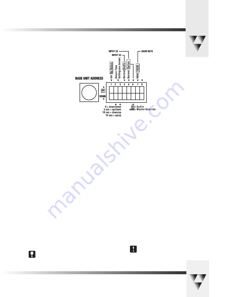
Configuring The Presets and Switches
Diagram showing DIP Switch configuration which can be defined on the
rear panel of the PRM.
Not Use
d
INPUT #33 OPERATION (DIP Switches 5,6):
Switch 5 is used to determine the operation mode of input 33.
• NORMAL– The input will operate as a normal input, identical
to inputs 1-31.
• OPTION– Then the operation is dependent upon the setting
of Dip Switch 6.
Switch 6 settings
• UP– The input will operate in an audio-only mode, which
causes no camera movement when the microphone is active.
When in audio-only mode, an active input will not cause the
VIDEO RELAY to be activated.
• DOWN– The input will operate as a Master Override input.
When this input is active, the camera will be positioned
to a Master Override position (preset 33) and all
other microphones will be “LOCKED” out from controlling
the camera. Once this input is released, control is
returned to all microphones and they are serviced as
usual. In this case, the video relay will remain open.
BAUD RATE SETTING (DIP Switch 7):
This switch determines the communication baud rate: UP = 19,200;
DOWN = 9,600
19,200 must be used if a PVTV SHOT Director or CameraMan
Control Center is connected to the system.
DIP Switch 8:
Not in use at this time.


