THOMSON Grass Valley ParkerVision CameraMan Installation And Operation Manual Download Page 11

Page 8

CameraMan® 1-CCD and 3-CCD Student Camera System Installation and Operations Manual  •  © 2000 ParkerVision, Inc.
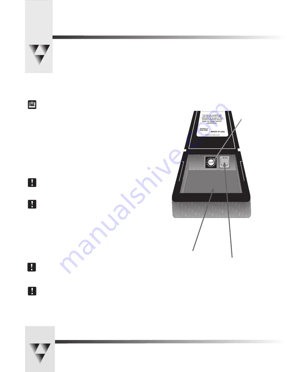
RJ-11 jack, for 

hard-wired mode

Battery compartment

Keypad Address

Setting Up the Camera Control Keypad

Step 1:  

Adjust the KEYPAD ADDRESS rotary switch (located in the battery compartment 

of the keypad) so the selected setting corresponds to the setting of the BASE UNIT 

ADDRESS switch on the back of the Camera, and the front of the PRM.

See Also:

 For information on how to set the Base Unit Address on your CameraMan 

camera, refer to the CameraMan’s installation and operations manual.

Step 2:  

Connect the Keypad to meet your needs.


For Wireless RF Mode (up to 60 feet): 

•    Install the supplied AA batteries in the Camera Control Keypad by removing 

the battery door and inserting the battery into the battery compartment as 

indicated. 

•    Replace the battery door. 

•    Press one of the PAN/TILT arrows on the keypad and verify that the LED on 

the front of the keypad illuminates. This indicates that the battery is installed 

properly. 

Note: 

 If the light does not illuminate, the battery may be installed backwards. Reverse 

the way the battery is inserted, and try again.  If a low battery is installed, the keypad 

will emit a long beep.

Note: 

 If the battery is inserted improperly, it 

will not

 damage the keypad. The keypad 

will simply not work.


For Hard-wired Mode (up to 250 feet):

•    Remove the batteries.

•    Connect a CameraMan Keypad Cable (included) to the RJ-11 type jack located 

in the battery compartment of the Keypad. 

•    Connect the other end of the cable to the PVI Com port on the CameraMan 

base unit.


Note:

 When the system is powered on, the light on the keypad should illuminate 

momentarily, indicating the keypad is ready for operation.  The light located above the 

PVI COM port on the base unit is used to indicate communication activity.

Note:

  You MUST remove the batteries in the Camera Control Keypad when it is being 

used in the hard-wired mode.


Your Camera Control Keypad is designed to be used in either a wireless, or hard-wired mode. The wireless mode allows you to 

move freely about the room, while the hard-wired option gives you the ability to control the camera from greater distances. For 

either, follow the steps below to prepare your keypad for use with your Student Camera System.

Summary of Contents for Grass Valley ParkerVision CameraMan

Page 1: ...1 CCD and 3 CCD Student Camera System Installation and Operations Manual L1209101 rev A FEBRUARY 2005...

Page 2: ...nloaded FAQ Database Solutions to problems and troubleshooting efforts can be found by searching our Frequently Asked Questions FAQ database Software Downloads Software updates drivers and patches can...

Page 3: ...eshooting 10 11 t A Specifications 11 t B Typical Student System Diagram 12 t C Warranty Information 13 The terms Visibly Better System II IMAGE WhisperDRIVE Plus and General Pan Tilt Camera System an...

Page 4: ...s it difficult for instructors at the far end to differentiate one student from the next and determine exactly which student is speaking With CameraMan each individual student can simply press the My...

Page 5: ...kground noise and cause unwanted camera motion The PRM works on a first come first served basis so when two or more students activate their microphones at the same time the first microphone activated...

Page 6: ...Switch t 16 position rotary switch used to tell the PRM which camera it controls It should match the Base Unit Address switch on the CameraMan camera The Factory Default is zero 0 DIP Switches t Used...

Page 7: ...tely 0 15 off the end of the wire 2 Insert the wire into the screw terminal slot on the connector plug 3 Tighten the terminal screw 4 Repeat steps 1 3 for the other 4 wire pairs in that connector bloc...

Page 8: ...act closure would connect to a video switcher To Connect the Audio or Video Relay 1 Connect one end of a 2 conductor cable to the green connector block Strip a short section approximately 0 15 off the...

Page 9: ...8 9 10 11 12 13 14 15 16 17 18 19 20 21 22 23 24 25 26 27 28 29 30 31 32 33 Audio Relay Video Relay 0 1 2 345 6 7 8 9 A B C D E F 1 2 3 4 5 6 7 8 BASE UNIT ADDRESS 8 7 6 5 4 3 2 1 SET DOWN NO RETURN...

Page 10: ...d for use by someone who wishes to be heard but does not want to cause the camera to position on them such as a room facilitator Configuring The Presets and Switches Diagram showing DIP Switch configu...

Page 11: ...the light does not illuminate the battery may be installed backwards Reverse the way the battery is inserted and try again If a low battery is installed the keypad will emit a long beep Note If the ba...

Page 12: ...e the manual ZOOM buttons to set the needed Zoom perspective 4 Only when desired use the manual IMAGE buttons to set the needed light dark contrast 5 Input the Location Preset number 1 33 that corresp...

Page 13: ...s first plugged in 5 Be sure that you have pressed the appropriate CAMERA SELECT button on the Keypad corresponding to the camera you wish to control If only using one camera be sure to press CAMERA S...

Page 14: ...positive and negative leads on the cable connecting that the microphones to the PRM are lined up correctly with the contact closure leads on the PRM Specifications KEYPAD RF CONTROL OPTION RF Range 6...

Page 15: ...ystem INPUTS OUTPUTS RS 4 85 DC POW ER 1 2 3 4 5 6 7 8 9 10 11 12 13 14 15 16 17 18 19 20 21 22 23 24 25 26 27 28 29 30 31 32 33 Audio Relay Video Relay 0 1 2 34 5 6 7 8 9 A B C D E F 1 2 3 4 5 6 7 8...

Page 16: ...nal product The warranty is non transferable Purchaser s failure to make a claim as provided above or continued use of the product shall constitute an unqualified acceptance of such product and a waiv...

Page 17: ...Page 14 CameraMan 1 CCD and 3 CCD Student Camera System Installation and Operations Manual 2000 ParkerVision Inc Notes...

Page 18: ...2000 ParkerVision Inc Literature Part Number L1209101 ref LPMCSC13 Revision D...

Reviews: