2-37
2
1
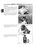
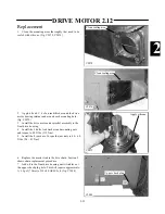
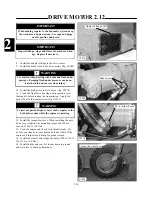
Place the drive motor in a vise with the output shaft
facing down. Clamp the motor to the vise, holding it by
the mounting flange area. Do not clamp the motor on the
housing as excessive pressure will cause distortion.
2
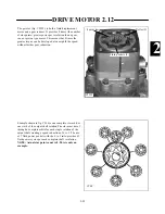
Mark a line across the various sections of the drive
motor to assist in reassembly. (fig. C2287)
5
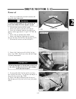
Remove the 4 bolts from the drive motor valve hous-
ing. (fig. C2290) Upon reassembly, torque the bolts in a
criss cross pattern at 130 ~ 135 ft lbs. (177 ~ 183.5 Nm)
DRIVE MOTOR 2.12
C2287
C2288
C2289
C2290
Remove section bolts
Disassembly
4
Insert an allen wrench into the open hole and remove
the set screw restrictor. (fig. C2289)
3
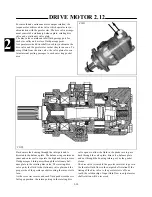
Remove the small allen head socket plug located
between two of the section bolts.( fig. C2288)
Mark sections
Remove restrictor plug
Remove restrictor

