1
Control Valve Disassembly 137/153
1-24
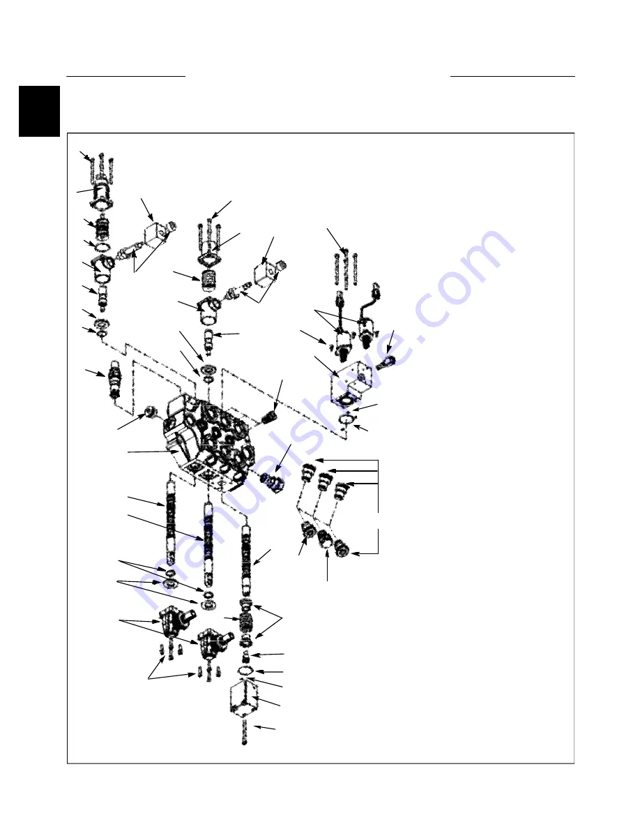
CONTROL VALVE 1.3
1. Main relief valve
2. O ring seal
3. Ring
4. Positioner kit joint
5. Positioner kit spacer
6. O ring seal
7. Lift positioner kit
8. Lock assembly
9. 12 VDC coil
10. Lift endcap kit
11. M5 x 65 screw
12. SAE 10 plug
13. Valve body
14. Lift spool
15. Tilt spool
16. Lever box
17. M5 x 20 screw
18. Tilt endcap kit
19. Tilt positioner kit
20. Load check valve
21. Backpressure valve
22. Blanking plug
23. Anti cavitation valve
24. O ring seal
25. O ring seal
26. Control body
27. Joint
28. 12VDC pressure reducing
solenoid valve
29. M4 x 10 screw
30. M5 x 80 screw
31. Auxiliary spool
32. Control spring
33. Control bushing
34. Control screw
35. Control endcap
36. M5 x 65 screw
Diagram Legend
1
2
5
3
4
7
6
8
9
2
3
10
14
11
18
16
13
12
17
21
19
2
3
4
5
11
8
9
20
24
23
25
26
22
22
27
29
28
30
33
32
36
35
34
31
23
24
C4236
15


