background image

13 


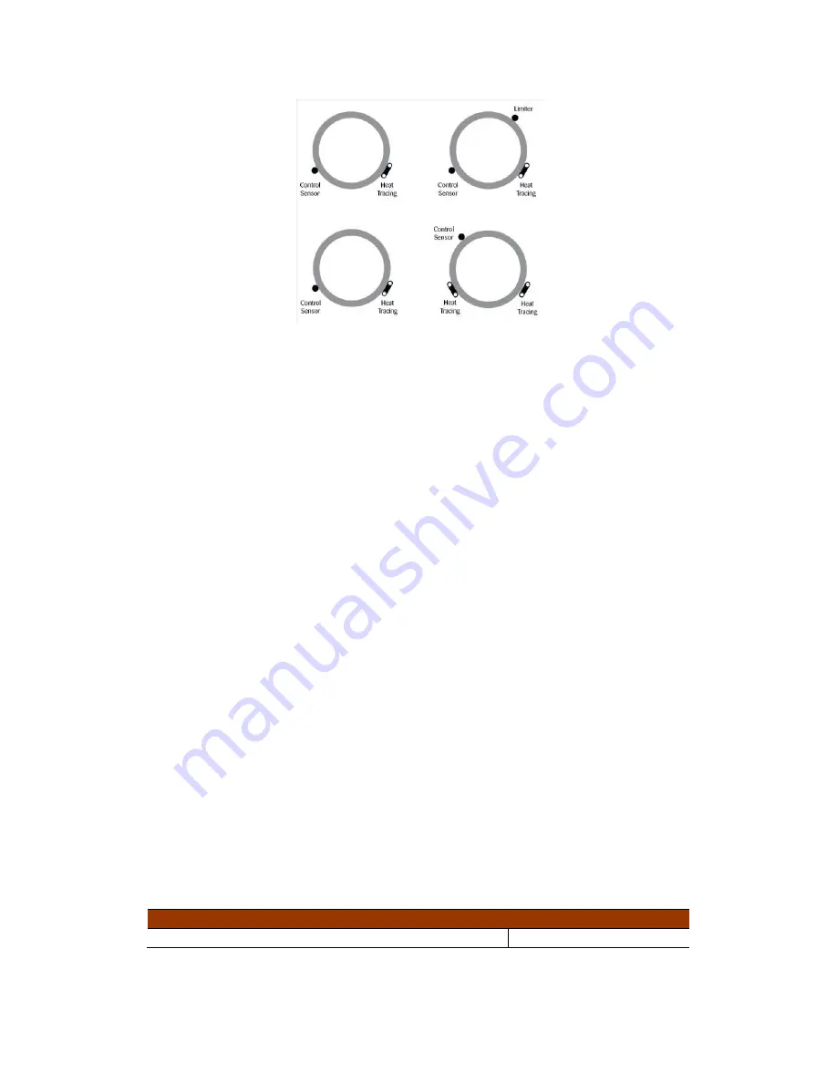
Figure 4.1: 

RTD Sensor Location


Where RTD sensors are installed on the process piping, follow the guidelines 
above.  In special cases where the limiting temperature sensor is to be installed 
on the heater itself, it is important to recognize that an offset should be 
anticipated in the trip set-point to allow for sensor reading error and overshoot. 

As a general rule, field RTD wiring and power wiring should not be routed in the 
same conduit or proximity in a tray as the temperature signals can become 
distorted and result in improper readings. 

4.3 Power Distribution Wiring and Breakers 

All field power wiring materials used shall be suitable for the intended service and 
shall be rated for insulation service temperatures up to and exceeding 221°F 
(105°C) unless higher values are otherwise noted in project specifications.  
Power supply wiring from the power transformers to the power distribution panel 
and distribution wiring to the heat trace circuits shall be rated for the heat trace 
use voltage or higher and shall be of a sufficiently large wire size to minimize 
voltage drop.  Heat trace circuit breakers should be selected based on the type of 
heat trace used, the service voltage, and the circuit current draw characteristics.  
It is especially important when using self-regulating trace heaters to make sure 
that the circuit breaker response curve type is coordinated with the startup 
characteristic of the trace heater in a cold start condition.  TCM2 controller circuit 
breakers should have current ratings no higher than 15 A.  In addition to the 
controller circuit breaker, every heat trace circuit shall be provided with a circuit 
breaker as a means for disconnection.  All circuit breakers shall be easily 
identifiable and accessible.  All distribution wiring connections should be 
tightened using a torque indicating screw driver to the levels indicated in 

Table 

4.1

Table 4.1: 

Recommended Torque Values


Location of Terminals 

Torque Values (Typical)* 

Distribution Equipment 

13.2 to 15.9 in. lbs.  1.49 to 1.80 N-m 

Summary of Contents for TraceNet TCM2

Page 1: ...TraceNetTM Control and Monitoring System TCM2 Installation Start Up Operating and Maintenance Guide ...

Page 2: ......

Page 3: ...ors or inaccuracies that may appear in this guide This document may not in whole or in part be copied photocopied reproduced translated or reduced to any electronic medium or machine readable form without prior consent in writing from Thermon Manufacturing Company This document is subject to change without notice Written and designed at Thermon Manufacturing Company 100 Thermon Drive San Marcos TX...

Page 4: ...ring 12 4 1 Heat Trace and Insulation Installation 12 4 2 RTD Installation and Wiring 12 4 3 Power Distribution Wiring and Breakers 13 4 4 TraceNet Panel Wiring 14 4 5 Serial Communication Wiring 14 5 Monitoring Heat Tracing Circuit Status 16 5 1 The Interface 16 5 2 Basic Navigation 18 5 3 Alarms 18 5 4 Trips 19 6 Accessing Control Settings 22 6 1 Password Protection 22 6 2 Adjusting Set points 2...

Page 5: ...ingle Circuit 3 Phase 30 8 The TCM2 Data Highway Communications 31 9 System Start Up 33 9 1 Initial Start Up Procedure 33 9 2 Troubleshooting Tips 33 10Maintenance 34 10 1 Safety Precautions 34 11Notes 35 12Appendix A Memory Map 36 13Appendix B Additional Information 41 14Appendix C Troubleshooting Tips 42 ...

Page 6: ... Initial Inspection and Handling Upon receiving the TraceNet TCM2 control panel it is important to confirm that the contents of the shipping containers agree with the shipping documents and with the purchase order Also it is important to check the shipped container exterior and packing materials for any possible freight damage Where damage is observed take photos and notify the carrier as well as ...

Page 7: ...olted in place the panel is ready for final configuration wiring and site required assembly Note that the TCM2 control and monitoring module is normally shipped in special packaging to minimize any undue impact stress during shipment It should be removed from its packaging being attentive to any shipping damage that may have occurred during its transit Warning Heat Sink Temperatures May Exceed 60 ...

Page 8: ...gh and Low Current o High Ground Earth Leakage Current o Circuit Fault o Damaged Temperature Sensor Trip Functions o High Temperature o High Current o High Ground Earth Leakage Current 3 phase Current Monitoring1 The TCM2 s four line display tri color status LEDs and four button interface offer the operator intuitive access to the heat tracing system operating parameters including heat trace statu...

Page 9: ...tains an internal 3 15 Amp 250 V fuse that is designed to be serviced only at the factory The TCM2 module can be utilized in a variety of TraceNet control and monitoring systems Specific wiring and equipment arrangement details are provided in drawings included within the TCM2 Series panel at the time of shipment The TCM2 module is also backward compatible and may be used as an upgrade within lega...

Page 10: ...ater Current Through Each Solid State Relay Temperature Inputs Up to Two per Control Point Platinum RTDs 100 Ω 32 F 0 C Temperature Control Range 200 F to 1112 F 129 C to 600 C Alarm Contact Relays 24 VDC 200 mA Communication RS 485 ModBus ASCII or RTU up to 57600 Baud Control Methods On Off MEC On Off SSR Proportional Ambient or APCM Display 4 Line 20 Character OLED Relative Humidity 0 to 90 Non ...

Page 11: ...C Communication RS 485 ModBus ASCII or RTU up to 57600 Baud Accessory Power Output 9 W 24 VDC Digital Alarm Outputs 3 x 24 VDC 100 mA Control Outputs 2 x 24 VDC 100 mA or 2 x 12 VDC 100 mA user selectable Control Methods On Off MEC On Off SSR Proportional Ambient or APCM Display 4 Line 20 Character OLED Operating Temperature 40 F to 140 F 40 C to 60 C Storage Temperature 40 F to 176 F 40 C to 80 C...

Page 12: ...s Enclosure Option Module Type SSR30A single pole relay SSR15A double pole relay SSR30B single pole relay SSR15B double pole relay SSR50C Up to 3 single pole relays 1 2 3 SSR30B 2R single pole relay 40 F 4 C 104 F 40 C 40 F 4 C 104 F 40 C 40 F 4 C 104 F 40 C 40 F 4 C 104 F 40 C 40 F 4 C 104 F 40 C 40 F 4 C 104 F 40 C P2 SS2 TCM2 1 30 19 22 9 30 30 24 15 30 25 P3 SS3 TCM2 1 30 24 24 12 30 30 24 15 ...

Page 13: ...ches Dimensions mm P2 Fiberglass 4X IP54 12 x 14 x 6 305 x 356 x 152 SS2 Stainless Steel 4X IP54 12 x 14 x 6 305 x 356 x 152 P3 Fiberglass 4X IP54 16 x 14 x 6 406 x 356 x 152 SS3 Stainless Steel 4X IP54 16 x 14 x 6 406 x 356 x 152 SS4 Stainless Steel 4X IP54 36 x 30 x 16 914 x 762 x 406 ...

Page 14: ...connected to field wiring Care must be taken to avoid exceeding the temperature rating of the TCM2 Refer to Table 2 3 for panel current ratings 3 1 Bottom Side Connections 1 POWER Mains supply input accepts 100 240 V at 50 60 Hz L1 is Line 1 L2 is Line 2 or Neutral and the symbol is the protective conductor ground connection 2 24 VDC DIGITAL OUTPUTS A 24 VDC output is provided to power accessories...

Page 15: ...for entering factory test mode when connected to the isolated RS 485 Right Pin D Middle Pin S Left Pin D 4 AUX IN Provides connection for optional factory installed externally mounted interface buttons See Appendix B for wiring diagram 5 FACTORY This port is for factory programming only 6 COMM LED Indicates traffic on the isolated data highway RS 485 3 2 Top Side Connections RTD field wiring shoul...

Page 16: ...ning the panel It may be connected to a pushbutton switch or to the contacts of a relay driven by a remote signal The positive side provides an isolated 5 VDC signal When switched the negative side drives the diode of an opto coupler to signal to the TCM2 acknowledgement of the alarm or trip RS 485 DATA HWY D D are the differential bus lines for communications S is the common leg and is often conn...

Page 17: ...ring RTD control sensors should generally be installed on the process lines or in ambient where ambient sensing is applied in a location that is most representative of the entire heat trace circuit In general it is recommended that the sensors not be located at heat sinks such as pipe supports pumps and valves as the control system response needs to be based on the majority of the process line The...

Page 18: ...nd distribution wiring to the heat trace circuits shall be rated for the heat trace use voltage or higher and shall be of a sufficiently large wire size to minimize voltage drop Heat trace circuit breakers should be selected based on the type of heat trace used the service voltage and the circuit current draw characteristics It is especially important when using self regulating trace heaters to ma...

Page 19: ...ated for insulation service temperatures of at least 221 F 105 C unless higher values are otherwise noted in project specifications All TraceNet component terminal block connections should be tightened using a torque indicating screw driver to the levels indicated in Table 4 1 4 5 Serial Communication Wiring TraceNet TCM Series panels may be linked together for communications with an RS 485 commun...

Page 20: ...er jacket Belden 3107A or equal 120 ohm 30 C to 80 C 22 F to 176 F 24AWG PE insulation PVC outer jacket Belden 9842 or equal 120 ohm 70 C to 200 C 94 F to 392 F 24AWG Teflon FEP insulation Teflon FEP outer jacket Belden 89842 or equal Note All these products are designated as 120 ohm impedance for balanced line communication uses ...

Page 21: ...e at Start Up After this start up message the TCM2 will immediately begin normal operation and display the Circuit Screen Once the Circuit Screen is shown the TCM2 will control each enabled circuit according to its set points Figure 5 2 describes the information shown on a typical Circuit Screen in normal operation with two RTD s on Circuit 1 and no alarms If any alarms are present a corresponding...

Page 22: ...Red Heater OFF No Alarms Heater ON One or more Unacknowledged ALARM Present One or more Acknowledged ALARM Present Unacknowledged TRIP or RTD fault Acknowledged TRIP or RTD Fault Main Menu Enters Main Menu Returns to Circuit Screen from Main Menu Returns to Main Menu from Submenu Up and Down Arrow Keys Navigation Value Changes Acknowledge Accept Key Acknowledge Alarms Reset Trips Enter Submenu Acc...

Page 23: ... See Table 6 1 in Part 6 Accessing Control Settings for a list of Main Menu Options 5 3 Alarms In the event that the measured conditions of the heat trace circuit fall outside the user defined parameters the TCM2 will notify the user in four ways the Alarm Line of the display tri color LEDs digital outputs and through RS 485 communications When an alarm condition first occurs the corresponding tri...

Page 24: ...the TRIP causing the circuit LED to stop flashing and stay solid red and the common TRIP digital output to deactivate To reset a high temperature TRIP and reactivate the circuit must be pressed again For heater current and ground earth fault TRIPs pressing will reset the TRIP cause the common TRIP digital output to deactivate the circuit LED to stop flashing red and the TCM2 will attempt to resume...

Page 25: ... equal to the HIGH TEMPERATURE ALARM set point but has not yet risen above a value equal to the HIGH TEMPERATURE TRIP HIGH set point HIGH TEMP TRIP HIGH HIGH TEMP If HIGH TEMPERATURE TRIP is ON OFF this message will be displayed if the measured temperature rises above a value equal to the HIGH TEMPERATURE TRIP HIGH set point HIGH GROUND CURR The measured ground earth leakage current has risen abov...

Page 26: ...s higher than the HIGH CURRENT ALARM set point but not above the HIGH CURRENT TRIP HIGH HIGH AMPS TRIP HIGH HIGH AMPS If HIGH CURRENT TRIP is ON OFF this message will be displayed if the measured heater current is higher than the HIGH CURRENT TRIP HIGH set point CKT FAULT ALARM Indicates that a control relay was nonresponsive during a SELF TEST or that heater current was detected when the circuit ...

Page 27: ...tion is disabled The first line of the Main Menu displays whether the control module is in View Mode or Program Mode See Figure 6 1 To enable the password enter the Main Menu and select PASSWORD SETTINGS Change PASSWORD from OFF to ON and enter a password using to change each number and to select the number and confirm Figure 6 2 Enable Disable Password or Change Password 6 2 Adjusting Set points ...

Page 28: ...vailable for editing Use to change the value and to accept the new value and advance the cursor to the next set point or setting available for editing When finished editing within a submenu use to return to the Main Menu When finished making changes press to return to the Circuit Screen from the Main Menu ...

Page 29: ...GH TEMPERATURE TRIP HIGH 1 HIGH TEMP SEEN RESET Y or N 1 LOW TEMP ALARM Individual Circuit LOW TEMP ALARM 200 F or 200 C to MAINTAIN TEMP 1 LOW TEMP SEEN RESET Y or N 1 GROUND CURRENT Individual Circuit GROUND CURRENT real time ground earth fault current measurement 0 225 mA 1 mA TRIP or HIGH HIGH is a higher level alarm if GROUND CUR TRIP is OFF GROUND CURRENT ALARM to 225 mA 1 mA GROUND CURRENT ...

Page 30: ...PCM See Section 7 1 for Control Method CONFIGURATION Both Circuits GROUND CUR TRIP ON or OFF HEATER CUR TRIP ON or OFF HIGH TEMP TRIP ON or OFF ALARM ON Digital Outputs Activate On ALL ALARMS or TEMP ONLY ALARM OUTPUT NRM Alarm Outputs Normally ON or OFF RTD UNITS Temperature Units C or F APCM CYCLE TIME 20 25 or 33 min AUTO SELF TEST OFF or every 2 99 hours 1 hour START UP DELAY 0 30 min 1 min SO...

Page 31: ...200 38400 57600 ENTER PASSWORD Controller in View Mode PASSWORD 0000 9999 PASSWORD SETTINGS Controller in Program Mode PASSWORD ON or OFF enable or disable password protection NEW PASSWORD 0000 9999 DEFAULT OLD PASSWORD OTHER SETTINGS See below Seen after New Password Entered OTHER SETTINGS Controller FIRMWARE version Major Minor version HOURS IN USE Time on from manufacture CID Chip Identifier Fa...

Page 32: ...at trace ON OFF SSR ON OFF SSR adds the Soft Start feature to ON OFF control This control method takes advantage of the Solid State Relay s high switching life to decrease temperature overshoot Under ON OFF SSR control the heat trace will turn on and off the same way it does in ON OFF but will gradually increase the duty cycle by way of cycle omission from 18 to 100 The duration of this gradual in...

Page 33: ...plete explanation of the CONTROL options Use to choose the desired Control Method and to accept the change and move the cursor back to the top of this submenu From here another circuit may be selected or press to return to the Main Menu 7 3 The TCM2 in Process Sensing Applications The control method which provides the most tightly controlled temperature and highest energy efficiency is Proportiona...

Page 34: ... 100 to 40 F 40 C HEATER OFF would be set to 50 F 10 C A feature unique to the TCM2 among TraceNet controllers is the capability of using mechanical relays for ambient control When using mechanical relays the ambient algorithm changes the period over which duty cycle is adjusted Instead of using cycle omission over a period of about one second the duty cycle period is set to a cycle time of 20 25 ...

Page 35: ...ability to directly monitor all three phases of a 3 phase system In this single circuit 3 phase option the TCM2 will monitor and display all three current readings on the Circuit Screen Once configured for 3 phase operation there are no additional options to configure to begin normal operation A high or low current condition on any phase or ground earth fault condition will result in an alarm or t...

Page 36: ... and settings in the TCM2 including the ability to remotely view all parameters in real time1 acknowledge alarms and reset tripped circuits The TCM2 Data Highway uses Modbus over RS 485 a world wide standard in reliable industrial communications Available with two user selectable protocol configurations and four common Baud rates the TCM2 is ready to be integrated into the vast majority of current...

Page 37: ...e same network as legacy Thermon HeatChek systems 19200 38400 or 57600 For best results a 120 Ω shielded twisted pair cable is recommended The Data Highway port on the TCM2 is isolated to 5 kVrms with protection against ESD to 15 kV For shielding to be effective the shield should be grounded on one side but not on both TCM2 panels can also be configured with reliable serial to Ethernet converters ...

Page 38: ...e circuits are disconnected at the circuit breakers This is done to provide protection from higher voltages while maintaining power so that the installer may program the controller 9 2 Troubleshooting Tips When starting up a newly installed heat trace and control and monitoring system it is not uncommon to encounter numerous alarm and trip events Data entry errors unanticipated temperature oversho...

Page 39: ... tracing and control circuit of interest is fully de energized and the equipment is grounded See Section 9 1 for more information If it becomes necessary to service or test live equipment the following instructions must be followed Use one hand when servicing the equipment Accidental death or severe injury may occur especially if a current path is created through the body from one hand to the othe...

Page 40: ...35 11 Notes ...

Page 41: ... RTD Circuit 1 04 109 Control RTD Circuit 2 04 110 Ground Earth Current Circuit 1 04 111 Ground Earth Current Circuit 2 04 112 Percent ON Circuit 1 04 113 Percent ON Circuit 2 04 114 Heater Current CT 1 04 115 Heater Current CT 2 04 116 Heater Current CT 3 117 119 No data 04 120 Alarm Status Circuit 1 04 121 Temp RTD1 Circuit 1 Temp Value x 10 04 122 Temp RTD2 Circuit 1 Temp Value x 10 04 123 Cont...

Page 42: ...12 3 Trips Enable Disable Bits 15 14 13 12 11 10 9 8 7 6 5 4 3 2 1 0 High Current Trip Not Used Circuit OFF Ground Earth Fault Trip High Temp Trip RTD2 High Temp Trip RTD 1 RTD2 Fault RTD1 Fault High Current Alarm Low Current Alarm Circuit Fault Ground Earth Fault Alarm High Temp Alarm RTD2 High Temp Alarm RTD 1 Low Temp Alarm RTD 2 Low Temp Alarm RTD 1 15 14 13 12 11 10 9 8 7 6 5 4 3 2 1 0 Heater...

Page 43: ...1 03 15 Low Temp Alarm RTD 1 Circuit 2 03 16 Low Temp Alarm RTD 2 Circuit 1 03 17 Low Temp Alarm RTD 2 Circuit 2 03 18 High Ground Earth Current Trip Circuit 1 03 19 High Ground Earth Current Trip Circuit 2 03 20 High Ground Earth Current Alarm Circuit 1 03 21 High Ground Earth Current Alarm Circuit 2 03 22 High Current Trip Circuit 1 03 23 High Current Trip Circuit 2 03 24 High Current Alarm Circ...

Page 44: ... Enable Disable Circuit 2 03 0x0028 40 High Temp Seen RTD 1 Circuit 1 03 0x0029 41 High Temp Seen RTD 1 Circuit 2 03 0x002A 42 High Temp Seen RTD 2 Circuit 1 03 0x002B 43 High Temp Seen RTD 2 Circuit 2 03 0x002C 44 Low Temp Seen RTD 1 Circuit 1 03 0x002D 45 Low Temp Seen RTD 1 Circuit 2 03 0x002E 46 Low Temp Seen RTD 2 Circuit 1 03 0x002F 47 Low Temp Seen RTD 2 Circuit 2 Table 12 5 Circuit Status ...

Page 45: ...ere 03 2018 Screen Saver 2019 Max Off Current 03 2020 2021 No Data Here 03 2022 Relay Output Voltage 0 12 V 1 24 V 2023 No Data Here 2024 Hours in Use 03 2025 Start Up Delay 2026 Soft Start 03 2027 Ground Earth Fault Sensitivity 0 Most Sensitive 3 Least Sensitive 2028 2030 No Data Here 03 2031 Single Temp Alarms Should always 0 03 2032 High Temp Alarm Delay 2033 2035 No Data Here 03 2036 Alarm Rel...

Page 46: ...41 13 Appendix B Additional Information Figure 13 1 Program Mode Menu Figure 13 3 View Mode Menu Figure 13 2 External Keypad Wiring Diagram ...

Page 47: ...etting programmed or expected reading did not consider natural temperature overshoot associated with the control scheme Move control set point down to allow for overshoot or raise the high temperature alarm set point if approved by project engineer It may also be possible to decrease the control band on the control circuit or adjust the type of control from on off to proportional Improperly locate...

Page 48: ...e Compare to pipe or equipment temperature known by another probe or sensor If different the RTD sensor may need replacement Heat tracing over designed in heat output and or due to cable availability or natural design selections available This can result in higher than expected temperatures due to overshoot especially when used with on off control mode This can also occur in an ambient sensing con...

Page 49: ...t when approved by project engineer Damaged open or wet thermal insulation does not allow the heat provided to hold the desired temperature Repair damage to insulation Wrong insulation size type or thickness on all of circuit being traced Measure circumference of insulation divide by π and compare to insulation diameter charts for proper over sizing Check insulation type and thickness against desi...

Page 50: ...y offset When using a 90 degree RTD probe for diagnostics verify this measurement technique on a known pipe in the same general temperature range and insulation configuration Damaged RTD sensor Disconnect RTD sensor and measure resistance Compare to resistance tables for corresponding value of temperature Compare to pipe or equipment temperature known by another probe or sensor If different the RT...

Page 51: ... has failed shorted or has very low resistance Has lightning damaged the sensor Maybe the piping has had some welding going on nearby Maybe the RTD has gotten wet Replace RTD Communications Alarm The following summarizes some of the possible causes and solutions for heat tracing communications alarms Cause Possible Solutions Improperly set controller address duplicate addresses or improper configu...

Page 52: ...h operations manager High Current Readings Alarms The following summarizes some of the possible causes and solutions for heat tracing high current readings or alarms Cause Possible Solutions Self regulating heater or power limiting heater current may exceed set value during normal operation or start up operations Increase high current alarm set point if approved by project engineer For startup ope...

Page 53: ...esistance may be installed Check heater set tags or markings on heater cable against installation drawings As an additional check disconnect heater from power and measure DC resistance Heat tracing may be powered on wrong voltage Recheck heater supply voltage Current sensing circuitry may have encountered a problem Use a different current clamp type meter which is known to be accurate and do a com...

Page 54: ...ent alarm set point if approved by project engineer Loss of a branch of the heat tracing circuit Measure total current and each branch current Compare to design values Check all connections Breaker off Turn breaker back on after conferring with operations manager Heat tracing cable may have been exposed to temperatures in excess of their maximum temperature ratings excessive steam out temperatures...

Page 55: ... powered on wrong voltage Recheck heater supply voltage Current sensing circuitry may have encountered a problem Use a different current clamp type meter which is known to be accurate and do a comparative reading Investigate current measurement circuitry further Note that one should only read heater currents when the heater is 100 on Field heater wiring is improperly labeled and or connected such ...

Page 56: ...wire routing if only one wire has been run through the current sensing toroid Heat tracing power wires in a multiple circuit system improperly paired If the return currentwire in the toroid is from a different circuit the two heater currents will not cancel and leave only leakage to be measured Correct wiring Heat tracing circuit has higher than expected leakage due to circuit length or higher vol...

Page 57: ......

Page 58: ...Thermon Inc 100 Thermon Drive San Marcos TX 78666 U S A www Thermon com The information in this guide is subject to change without notice Thermon Form PN80514 0421 ...

Reviews: