background image

- 37 -

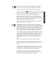
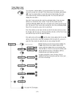
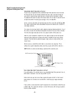
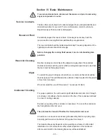
Troubleshooting

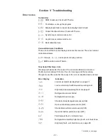
Section  V  Troubleshooting

Error Codes

On Start Up:

ROM checksum. Check with Thermo.

Test failure. Locks up the program.

Display board failure. Clears when display board is fixed.

Critical checksum failure. Check with Thermo.

Synchronous communication error

Asynchronous communicatio error

Bad calibration data

Unusual Hardware Conditions

These errors will flash on the display and cannot be cleared. These are internal
controller problems.

  through    

  - Interrupt errors during runtime.


 BOM invalid. Contact Thermo.

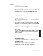
Functional/ Machine errors

Warnings self-clear after the cause of the error is identified and corrected.
Faults require pressing I/0 to clear the error message and then pressing
I/0 again to start the unit after the cause of the error is identified and corrected.

Error Display            Indication
 

Low temp setpoint warning/fault, see page 21


Low level warning, fluid below safe operating level


High temp setpoint warning/fault, see page 21

Refrigeration sensor shorted

Refrigeration sensor open

Shorted external temperature sensor (rtd2)

Open external temperature sensor (rtd2)

Shorted internal temperature sensor (rtd1)

Open internal temperature sensor (rtd1)

Fluid low level fault - unit shuts down

Refrigeration assembly high temp fault - unit shuts down

High temp fault - unit shuts down, see page 28

Continued on next page.

Summary of Contents for NESLAB RTE Series

Page 1: ... Maintenance Thermo Manual P N U00694 Rev 05 20 04 NESLAB RTE Series Refrigerated Bath Circulators No part of this publication may be repro duced or reprinted except for personal use without the prior permission of Thermo Electron ...

Page 2: ...2 Computer Setup Loop 24 Timer Setup Loop 25 Offset Setup Loop 26 Analog A I O Port Optional 27 High Temperature Cutouts 28 Nitrogen Purge 29 Accessories 29 Section IV Basic Maintenance Reservoir Fluid 33 Reservoir Cleaning 33 Algae 33 Condenser Cleaning 33 Internal Temperature Sensor rtd1 Calibration 34 External Temperature Sensor rtd2 Calibration 35 Optional Analog Port Calibration Optional 36 S...

Page 3: ...ron Corporation is committed to customer service both during and after the sale If you have questions concerning the unit operation contact our Sales Department If your unit fails to operate properly or if you have questions concerning spare parts or Service Contracts contact our Service Department Before calling please obtain the following information unit BOM number______________________________...

Page 4: ...ail us at neslabmanuals thermo com Be sure to include the manual part number and the revision date listed on the front cover Warranty Units have a warranty against defective parts and workmanship for 24 months from date of shipment See back page for more details NES care Extended Warranty Contract Extend parts and labor coverage for an additional year Worry free operation Control service costs Eli...

Page 5: ...than those described in this manual may result in a hazardous situation and may void the manufacturer s warranty Transport the unit with care Sudden jolts or drops can damage the refrigeration lines The units weigh approximately RTE 7 60 pounds 27 kilograms RTE 10 68 pounds 31 kilograms RTE 17 71 pounds 32 kilograms RTE 740 87 pounds 39 kilograms Units should be trans ported with equipment designe...

Page 6: ...al Plus controller only Press to sequence through the three indicators and accept the displayed value See page 17 NOTE None of the three setpoint indicators are visible unless this key is pressed Indicates heater status See page 17 Press to select external sensor See page 22 Digital Plus controller only Press to select the timer function See page 23 Digital Plus controller only Press to select the...

Page 7: ...n Locate the unit on a sturdy work area Ambient temperatures should be inside the range of 50 F to 104 F 10 C to 40 C The maximum operating relative humidity is 80 Never place the unit in a location where excessive heat moisture or corrosive materials are present The unit has an air cooled refrigeration system Air is drawn through the front panel and discharged through the rear panel The unit must...

Page 8: ... micro processortemperaturecontroller Specifications1 Temperature Range2 Temperature Stability3 Cooling Capacity4 Pump Capacity4 RTE7 RTE10 RTE 17 RTE 740 25 Cto 150 C 22 C to 150 C 40 C to 200 C 0 01 C General Information 40 30 20 10 0 10 20 30 40 5060 70 80 90100 Temperature C 1100 1000 900 800 700 600 500 400 300 200 100 Heat Removal Watts A 115 60 RTE 740 units B 230 50 RTE 740 units C RTE 7 1...

Page 9: ... 8 Time to Temperature 115V 60 Hz units 230V 50 Hz units RTE 740units General Information ...

Page 10: ... alcohol This fluid is HIGHLY flammable and is not recommended by Thermo Above 80 C baths are tested at with silicone oil This fluid is known to release a formaldehyde vapor which is carcinogenic above 150 C 3 20 C ambient 20 C bath temperature using water Sea level Measured at the center of the work area work cover on no external flow stable ambient full refrigeration RTE 740 in Energy Saving Mod...

Page 11: ...8 7 8 1 3 15 8 Unit Dimensions Dimension A Dimension B Dimension C Dimension D Dimension E Crate Dimensions D x W x H RTE 7 RTE 10 RTE 17 RTE 740 23 5 8 23 5 8 26 5 8 26 5 8 9 1 4 11 3 8 11 3 8 11 3 8 19 20 1 8 20 1 8 20 1 8 17 3 8 17 3 8 20 3 8 20 3 8 10 5 8 10 5 8 10 5 8 12 3 8 26 x 18 x 33 ...

Page 12: ... 30 centimeters at the front and rear of the unit is necessaryforadequateventilation Inadequateventilationwillreduce cooling capacity and in extreme cases can cause compressor failure Excessively dusty areas should be avoided and a periodic cleaning schedule should be instituted see Section IV Condenser Cleaning Using 20 C water as a bath fluid 115 60 units will retain their full rated capac ity i...

Page 13: ...pecified voltage 10 The RTE 7 is not designed to be used beyond the voltage range or have momentary power interruptions Install an un interruptible power supply or a line loss detection method All units are Pollution Category 2 OvercurrentProtectionII Thefollowingpoweroptionsareavailable Unit Amps1 Breaker Power Inlet RTE7 115 60 1 12 15A IEC320 C 13 100 50 60 1 12 15A IEC320 C 13 230 50 1 12 15A ...

Page 14: ...tz units do not come with a power cord set To select the proper power cord follow these guidelines nThe cord set must consist of a plug cable and receptacle nIf the unit is rated greater than 12 Amps use a cord set rated for 20A nIf the unit is rated less than 12 Amps use a cord set rated for 15A nThe cord set must be approved by local electrical authority or other acceptable agency nEnsure the pl...

Page 15: ...nt to keep the distance between the unit and the external system as short as possible and to use the largest diameter tubing practical Tubing should be straight and without bends If diameter reductions must be made make them at the inlet and outlet of the external system not at the unit If substantial lengths of cooling lines are required they should be pre filled with bath fluid before connecting...

Page 16: ...pump inlet will draw an occasional air bubble to prevent over flow and the pump outlet will force fluid through the submerged tube to preventaerationofthevessel To avoid siphoning the bath work area when the unit is shut off lift the leveling device out of the vessel and above the level of the unit Circulating through two closed loops The pump can be used to circulate through two closed loop syste...

Page 17: ...ene glycol propylene glycol silicone oil and filtered water are acceptable fluids NOTE Kinematic viscosity of the selected fluid should not exceed 50 centistokes at the lowest operating temperature Please call Thermo customer service to discuss high and low temperature fluid selections However we will often refer you to chemical companies specializ ing in heat transfer fluids Filling Requirements ...

Page 18: ...ll through the controller s LEDs It is also used to save new changes YES ARROW Use this key to increment numerical values when setting values and to accept new settings NO ARROW Use this key to decrement numerical values when setting values and to abort new settings Indicates refrigeration system status It illuminates to indicate the refrigeration system is removing heat from the bath fluid The in...

Page 19: ...e new setpoint value will rapidly flash for two cycles and then the controller will return to the reservoir fluid tempera ture display If SCROLL is not pressed within 60 seconds the change will time out and revert to the original setpoint The controller will automatically return to the reservoir fluidtemperaturedisplay NOTE You can not adjust the setpoint closer than 0 1 C of either temperature li...

Page 20: ...on is needed for operation above 50 C turn on the Full Range Cooling Mode See Setup Tuning Loop on page 21 to enable this feature To display change the setpoint press until illuminates The display will flash the current setpoint value Use the arrow buttons to change the value The controller will not allow you to enter a setpoint closer than 0 1 C of either temperature alarm setting see next page A...

Page 21: ...gh temperature alarm setting press until illuminates The display will flash the current setting value Use an the arrow buttons to change the value You can not set the alarm closer than 0 1 C above the setpoint Attempting to causes the indicator to flash and on Digital Plus controllers sounds the alarm On units with the Digital Plus controller pressing Mute prior to pressing SCROLL will abort any c...

Page 22: ...s all changes Thermo recommends that only a qualified technician change PID parameters Incorrect PID values will hamper unit perfor mance See page 40 for factory preset PID values Factory preset off Factory preset off Factory preset 0 1 Factory preset off Full range cooling mode allows the refrigeration to operate throughout the entire temperature range If off refrigeration is available only below...

Page 23: ...then return to the reservoirfluidtemperature NOTE The temperature display may drift for up to 10 15 seconds when transitioning between temperature sensors This is normal operation Serial Communication Pressing Computer enables disables the serial communications mode of operation In this mode all changes to the setpoint alarm limits etc must now be sent by a remote device using RS 232 or RS 485 pro...

Page 24: ... temperature displayed is an offset value NOTE The temperature offsetonly affects the displayed value when the offset mode is enabled the other setpoint values still dictate unit performance To setup the bath for offset mode operation see Offset Setup Loop on page 26 If you press the Offset button when an offset is 0 or not defined or if serial communications is enabled the button will flash the u...

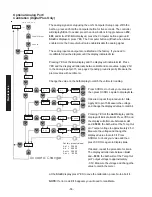
Page 25: ...aining parameters Press the arrow buttons to adjust any parameter When StorE is displayed press YES to accept any new values NO to abort them If the Computer button is not pressed for 60 seconds the function will time out and the changes will not be saved Pressing the Mute button will also exit the Computer Setup Loop and return you to the reservoir fluid temperature display Once enabled the Compu...

Page 26: ...the values NO to abort them If the Timer button is not pressed for 60 seconds the function will time out and the changes will not be saved Pressing the Mute will also exit the Timer Setup Loop and return you to the temperature display If the bath is turned off using with the timer mode enabled the Timer LED will go out and the timer mode will be disabled With the bath off you have to press the Tim...

Page 27: ...the Offset Setup Loop Press the Offset button to display the offset temperature and illuminate the LED NOTE Offset only changes the display of the enabled probe Setpoint and alarm values will display the non offset value Temperature control rapid heat and rapid cool functions will continue to use the non offset value If you press the Offset button when an offset is 0 or not defined or if serial co...

Page 28: ...rors 3 Status relay common 4 5 Not used 6 Analog Ground The analog ground is physically separated from the power ground throughout the unit To prevent offsets that result from ground currents the analog and power grounds are only connected at the unit s power supply Analog ground should only be used as a referencepin 7 Temp out The fluid temperature as measured by the enabled sensor can be read at...

Page 29: ...se and turn the power switch off then back on Start the unit Adjust the setpoint for a few degrees higher than the highest desired fluid temperature and allow the bath to stabilize at the temperature setpoint Turn the dial counterclockwise until you hear a click and the unit shuts down Before you can restart the bath it has to cool down a few degrees Then without moving the adjustment dial turn th...

Page 30: ...r level float switch and logic signal are already installed in the bath When tap water is available the bath is turned on and the fluid reaches the lower 1 inch horizontal level indicator located in the reservoir the autorefill begins filling the bath The autorefill shuts off when the fluid reaches the upper indicator or if the bath is turned off Description Part Number 100 115V 50 60Hz 6110120000...

Page 31: ...earance issue Afterthreadingtheoverflowassembly in as far as it goes loosen it back out until the Swagelok fitting is at the top Install one of the two supplied 4 40 x phillips head screws into the bottom of the drain housing where the stop screw use to be Make sure this screw is tight so that the assembly doesn t turn and drain the tank Reinstall the vertical tube assembly into the Swagelok if it...

Page 32: ...7 DIA 15 Lead Stainless Steel probe 126000000025 6 L X 187 DIA 20 Lead Stainless Steel probe 126000000029 6 L X 187 DIA 30 Lead Stainless Steel probe 126000000024 1 5 L X 187 DIA 30 Lead Stainless Steel probe 126000000033 GFCI Breaker Line Cords 115V 60Hz units only Unit Description Part Number 15 Amp Units 125V 15A4 6MA 126000000050 20 Amp Units 125V 20A4 6MA 126000000051 RS 232 485 Communication...

Page 33: ...sk top with the wall bracket removed Typical RPC Display COOL HEAT MENU SETPOINT 120 0 C BATH ON Description Part Number RPC100 115V 50 60Hz 1Ø 604012000401 with NEMA 5 15P type plug RPC100 240V 50 60Hz 1Ø 604028000401 requires country specific line cord not included 10 Cable Assembly included 083258 25 Cable Assembly 426000000029 50 Cable Assembly 426000000030 75 Cable Assembly 426000000031 100 C...

Page 34: ...nt may be used but the tank must be thoroughly rinsed Algae To restrict the growth of algae in the bath we recommend that all circulation lines be opaque This will eliminate the entrance of light required for the growth of most common algae We recommend the use of Chloramine T 1 gram per 3 liters Condenser Cleaning For proper operation the unit needs to pull substantial amounts of air through a co...

Page 35: ...the temperature to match the reference thermometer Press the SCROLL and NO buttons as shown until StorE is displayed press YES to accept the new value press No to abort it Repeat for the low end temperature Run the bath to a suitable low end calibration point At the r1 L display use the arrow buttons to adjust the temperature to match a calibratedreferencethermometer Press the SCROLL and NO button...

Page 36: ...OLL and NO buttons until StorE is displayed pressing YES accepts the new value Repeat for the low end temperature Run the bath to a suitable low end calibra tion point At the r2 L display use the arrow buttons to adjust the temperature to match a calibrated reference thermometer Pressing the SCROLL button after the low calibration will display StorE pressing YES accepts the new value If the SCROLL...

Page 37: ... SCROLL to check your value and then press SCROLL again to display A iL If desired repeat the procedure for A iL Apply 0V to pin 15 Measure the voltage and change the displayed value to match it Pressing YES at the AoUt display and the display will indicate A oH Press YES and the display will alternate between A oH and 2 5000 the bath will set the Temp Out pin 7 output voltage to approximately 2 5...

Page 38: ...gs self clear after the cause of the error is identified and corrected Faults require pressing I 0 to clear the error message and then pressing I 0 again to start the unit after the cause of the error is identified and corrected Error Display Indication Low temp setpoint warning fault see page 21 Lowlevelwarning fluidbelowsafeoperatinglevel High temp setpoint warning fault see page 21 Refrigeratio...

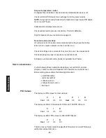
Page 39: ...If any other code appears contact Thermo customer service External Sensor Connector Digital Plus units are equipped with a male 9 pin D connector located on the rear of the control box The connector is used with an optional external sensor Troubleshooting Pin Function 1 3 wire RTD connection A 2 Noconnection 3 Noconnection 4 3 wire RTD connection A 5 Noconnection 6 Noconnection 7 3 wire RTD connec...

Page 40: ...entilationthroughthe front and rear panels is not impeded and the panels are free of dust and debris Ice build up on the cooling coils can act as insulation and lower the cooling capacity Raise the temperature of the bath to de ice the cooling coil and increasetheconcentrationofnon freezingfluid RTE 7 clicking Turn the unit off to initiate the 30 second refrigeration pressure equalization off dela...

Page 41: ...t See Appendix B Check all wiring for proper connections or possible shorts SoftwaretoverifyserialcommunicationisavailablefromThermo Service Assistance If after following these troubleshooting steps your unit fails to operate properly contact our Service Department for assistance see back cover Before calling please obtain the following information unit BOM number unit serial number softwareversio...

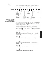
Page 42: ... calling Thermo for sales service information The controller can display the installed software version number For example for a unit with software version 082645 1A 1 Unit is running normally and displaying reservoir fluid temperature 2 Press and hold No for at least 10 seconds The display will show the first two digits for example 08 3 Press The display will show the remaining digits to the left...

Page 43: ...Blank Page ...

Page 44: ...Initially fill the tank with distilled deionized water Do not use untreated tap water as the total ionized solids level may be too high Maintain this water quality at a resistivity of between 1 to 10 megohm cm compensated to 25 C by using a purification system Although the initial fill may be as high as 18 megohm cm compensated to 25 C the desired level for long time usage is 1 to 3 megohm cm comp...

Page 45: ...crease the operating temperature range of the fluid but should not be used as a pre mixed anticorrosive solution Again this fluid does break down over time at high temperatures Dow uses a pH standard of 8 to base when the fluid has become corrosive Dowtherm is an ethylene based product that contains dipotassium phosphates in a 4 concentra tion The recommended use of Dowtherm is mixing with distill...

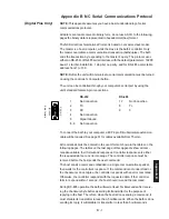
Page 46: ...und 6 9 NoConnection To connect the bath to your computer a M F 9 pin D Subminiature extension cable will be required See page 31 for cables available from Thermo All commands must be entered in the exact format shown in the tables on the following pages The tables on the last page of this Appendix show all com mands available their format and responses Controller responses are either the requeste...

Page 47: ...he one byte sum with FF hex The master requests information by sending one of the Read Functions as shown in Table 1 on page B 4 Since no data is sent to the bath during a read request the master uses 00 for the number of data bytes following the command byte The bath will respond to a Read Function by echoing the lead character address and command byte followed by the requested data and checksum ...

Page 48: ...s an RS 485 example if the master wants to set the setpoint to 30 C it would send Thebathresponds command byte 2 bytes to follow The checksum is the bitwise inversion of 22 00 03 F0 02 01 2C The temperature of 30 0 C is 300 decimal 012C hex CC 00 03 F0 02 01 2C DD CC 00 03 F0 03 11 01 2C CB command byte 3 bytes to follow The checksum is the bitwise inversion of 34 00 03 F0 03 11 01 2C The qualifie...

Page 49: ...imit CA 00 01 C0 02 d1 d2 cs CA 00 01 C0 03 qb d1 d2 cs SetHighTemperatureLimit CA 00 01 E0 02 d1 d2 cs CA 00 01 E0 03 qb d1 d2 cs Set Heat Proportional Band CA 00 01 F1 02 d1 d2 cs CA 00 01 F1 03 qb d1 d2 cs P 0 1 99 9 Set Heat Integral I 0 9 99 CA 00 01 F2 02 d1 d2 cs CA 00 01 F2 03 qb d1 d2 cs Set Heat Derivative D 0 5 0 CA 00 01 F3 02 d1 d2 cs CA 00 01 F3 03 qb d1 d2 cs Set Cool Proportional B...

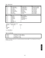
Page 50: ...ntrolling b 6 1 Alarm Muted Heat LED Flashing b 5 1 UnitFaulted Heat LED On b 4 1 UnitStopping Cool LED Flashing b 3 1 Unit On Col LED On b 2 1 Pump On 0 b 1 1 CompressorOn 0 b 0 1 HeaterOn 0 LED bits in REQ STATUS1 byte d5 LED State LEDFlashing LED On OFF 0 0 ON 0 1 FLASHING 1 1 Invalid 1 0 b 7 most significan bit b 0 least signifcant bit Table 3 Qualifier Byte 10 hex 0 1 precision no units of me...

Page 51: ...et reservoir tot het volgende niveau tussen dehorizontalemarkeringenopderoestvrijstalen scheidingsplaat die de werkruimte van het pompgedeeltescheidt Gebruiknooitbrandbareofanderekoelvloeistoffendie het toestel kunnen beschadigen De vloeistof die u gaat gebruiken moet een viscositeit hebben van 50 centistokes of minder bij lage temperatuur werking Kraanwaterwordtinhetalgemeenaanbevolen wanneer u b...

Page 52: ...proper installation or maintenance or to any unit that has been operated or maintained in any way contrary to the operating or maintenance instructions specified in Thermo s Instruction and Operation Manual This warranty does not cover any unit that has been altered or modified so as to change its intended use In addition this warranty does not extend to repairs made by the use of parts accessorie...

Reviews: