Performance Chip
Instruction Manual
P/N: 77-43035
Make:
Ford
Model:
F-250/F-350
Year:
2000
Engine:
V8-7.3L (td) Power Stroke
F-450/F-550
NOTE:
Manual Transmission Only!
Page 1: ...ance Chip Instruction Manual P N 77 43035 Make Ford Model F 250 F 350 Year 2000 Engine V8 7 3L td Power Stroke Make Ford Model F 450 F 550 Year 2000 Engine V8 7 3L td Power Stroke NOTE Manual Transmission Only ...
Page 2: ... any nature with respect to the products including without limitation lost profits lost sales loss of production property damage personal injury or loss or damage resulting from interruption or failure in operation of the products and BUYER hereby expressly waives and disclaims all such liability claims The BUYER acknowledges and agrees that the disclaimer of liability contained herein is a materi...
Page 3: ...ent Notes Page 3 To make sure you have the correct aFe POWER part number check your DPC number and or box code on ECM before installation ECU DPC 421 Supporting Box Codes BAW BIS DAC NBD QEK VRP VXY XPC and ZHL ...
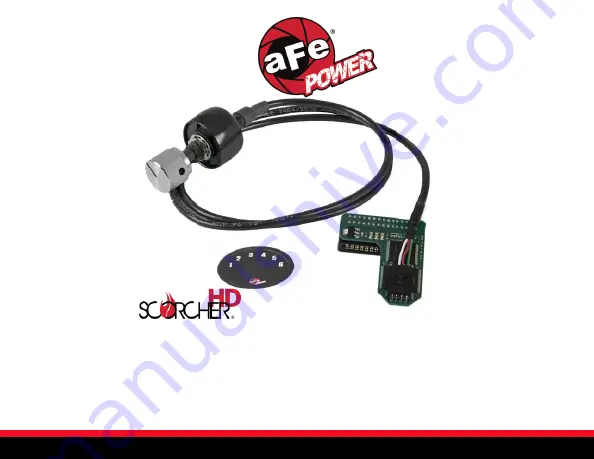
Page 4: ...Page 4 Parts List Page 4 2x Nylon Cable Ties Performance Chip Knob Switch Cable Position Switch Sticker Scotch Brite Pad ...
Page 5: ...Page 5 Chip Installation Page 5 BE AWARE All power to the vehicle must be DISCONNECTED prior to installation Failure to do so could result in damage to your vehicles ECM ...
Page 6: ...eries and locate the ECM Connector under the hood on the driver s side firewall Loosen the bolt 10mm socket located at the center of the ECM wiring harness plug Inside the truck remove the 2 bolts 7mm socket holding the ECM in place Remove the ECM from the truck ...
Page 7: ...leaned thoroughly or the chip will not make proper contact with the ECM Scrub off the coating using the Scotch Brite pad provided or a fine sandpaper The contacts should start to become shiny and metallic copper color Scrub only until you begin to see a hint of copper Wipe off any remaining coating with rubbing alcohol or lacquer thinner on a paper towel Please verify that BOTH sides of the edge c...
Page 8: ...Installing the Switch Chip Page 8 Slide the connector cable into the chip The proper orientation of the chip is with the circuit board of the chip and the switch cable on the larger side of the J3 port opening ...
Page 9: ...ure the chip to the ECM with a piece of package sealing or Duct tape Be sure the box holding the computer in place does not bind the chip causing it to tilt and lose connection Return the ECM to its location and re connect the wiring harness and 2 bolts in box Reconnect Batteries ...
Page 10: ...on Your installation is now complete Thank you for choosing aFe POWER 6 Position Settings 1 Stock Mode 2 High Idle Used to reduce wet stacking leading to excessive engine wear 3 50 HP 4 75 HP 5 100 HP 6 HOT Up to 133 HP Page 10 Switch Settings Page 10 ...
Page 11: ...Page 11 Page 11 Page left blank intentionally ...
Page 12: ...of the aFe POWER product Incidental or consequential damage means any loss expense or other damage that cannot be remedied by either repairing any defect in the aFe POWER product or by replacing the aFe POWER product Some states do not allow the exclusion or limitation of incidental or consequential damages so the above limitations or exclusions may not apply to you Furthermore no individual or en...
Page 13: ...252 Granite Street Corona CA 92879 MAIN TEL 951 493 7100 TECH 812 518 1220 E Mail Tech aFepower com 06 81247 ...