background image

SPECTRONIC 200E USER GUIDE

Using the Analyzer Mode

20

SPECTRONIC 200E User Guide

Thermo Scientific

The analyzer mode allows a laboratory manager to program sophisticated methods involving 
up


to four wavelengths, four factors, and a user–entered mathematical equation. Analyzer 

methods, once programmed, must be saved to a USB memory device for later re-use. The 
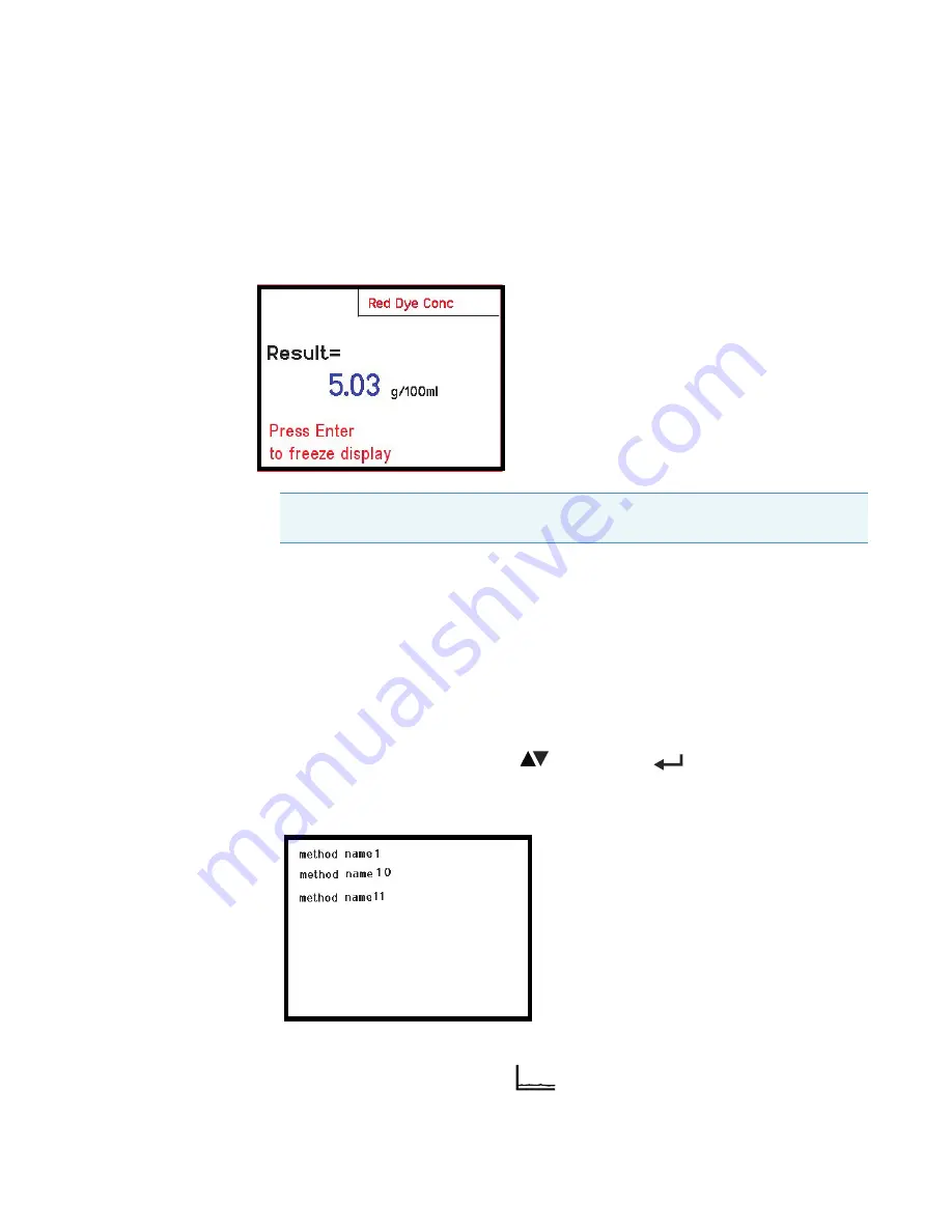
working screen of an analyzer method shows only the name of the method and the result 
(e.g.,

Figure 29

).

Figure 29. 

Using the Analyzer Mode

Loading a Saved Method

• If you select the 

Load Method

 option, the screen will display the names of all the 

methods saved on the attached USB memory device. 

• If no memory device is present, an error is returned. 

1. Select the chosen method using the 

 keys and press 

 to load it into the 

instrument.

Figure 30. 

2. After loading the method the instrument will prompt the user to place a blank solution in 

the sample compartment and press 

NOTICE    

Using the Analyzer mode requires that you store methods on a USB 

memory device that is formatted FAT32.

0.00

Summary of Contents for SPECTRONIC 200

Page 1: ...TU60001225 Revision A February 2013 UV Visible SPECTRONIC 200E User Guide...

Page 2: ...itten authorization of Thermo Fisher Scientific Inc The contents of this document are subject to change without notice All technical information in this document is for reference purposes only System...

Page 3: ...te 5 software The eight key membrane keypad and a 320 x 240 pixel graphical LCD display give the user full control over all functions of the instrument 1 nm data resolution over the wavelength range 3...

Page 4: ...oving parts to wear out or go out of alignment Convenient sample holders for cuvettes and test tubes Built in cuvette rack wells Technical Specifications Spectral Bandwidth 4 nm Light Source Tungsten...

Page 5: ...nections and indications on back panel of the instrument Figure 2 Safety warning label for lamp replacement Precautions for Safe Operation Power cable socket USB communication port Printer port Memory...

Page 6: ...ns cord for the power brick into a properly earthed grounded receptacle Plug the DC cable from the power brick into the receptacle on the back of the instrument next to the power switch Switching On P...

Page 7: ...appropriate error message is displayed with prompts to continue or restart the instrument For example Figure 6 See Initialization with Error Messages on page 36 for more detailed information Figure 6...

Page 8: ...has an 8 key membrane keypad and 320x240 pixel color graphics display Arrows and the central key are used to select menus and sub menus and to edit the numerical values Auto Zero This key is live in a...

Page 9: ...The screw clamp only needs to be adjusted once for a particular size of test tube 1 Loosen the thumb screw and place the test tube cuvette in the holder Home Takes the user directly to the Home menu...

Page 10: ...ighten 3 Remove the test tube and re insert it without adjusting the thumb screw The slide is locked down on only one side so it serves as a spring If the tube is held securely and slides in and out w...

Page 11: ...present in education models Scan Education models show absorbance readout to two digits after the decimal point Industry models show three digits after the decimal from 0 000A to 0 999A Select the mo...

Page 12: ...the knob or if desired A triangle marker and white line on the spectrum at the bottom of the screen show the color of the light presently being measured 6 Place a cuvette containing a blank solution...

Page 13: ...ation to observe absorption or transmission values of the sample at up to four different wavelengths in a single measurement Figure 12 1 Press once to select Measurement Mode Press to select either AB...

Page 14: ...the sample stage press and wait until the screen displays the message Performing Auto Zero The instrument will restart live display readings as soon as the auto zero measurement is complete 5 Remove...

Page 15: ...Mode ABS or T and the display unit Set the Measurement wavelength using or the knob The USB memory option allows you to select Save to automatically enter the method save sequence No to go directly to...

Page 16: ...e method has been loaded Figure 16 Figure 16 2 Follow the on screen instructions to auto zero the instrument The instrument will then go to the sample measurement screen Figure 25 Save and No Options...

Page 17: ...Use to set the concentration of each standard 3 Press to measure the ABS or T of that solution 4 After all standards have been measured the instrument prompts you to press to display the calibration...

Page 18: ...xecute the highlighted option If you select Save method the instrument will prompt to save the method or return to the standard graph screen If you select the Measure sample option the instrument goes...

Page 19: ...gure 23 7 Follow the directions on the screen to continue The standard graph will be displayed on the screen Figure 25 If no USB memory device is present the instrument will prompt you to connect one...

Page 20: ...measure a sample select Measure sample and press The screen will display both the concentration and measured ABS or T value as shown in Figure 25 Figure 25 9 If you select F in the No of STDs option t...

Page 21: ...sk for blank solution Figure 27 After performing an Auto Zero measurement the instrument shows the measurement screen Figure 28 Figure 28 11 Select the Measure sample option and press to measure each...

Page 22: ...f the method and the result e g Figure 29 Figure 29 Using the Analyzer Mode Loading a Saved Method If you select the Load Method option the screen will display the names of all the methods saved on th...

Page 23: ...rding Designing a New Method If you select the new method option Figure 31 the first screen in the method setup Figure 32 is where you specify the number of wavelengths and factors Figure 31 Figure 32...

Page 24: ...own in Figure 33 to proceed to the wavelength editing screen Figure 34 Figure 34 The screen displays as many wavelengths as you specified in the previous menu Use the keys to switch between measuremen...

Page 25: ...mula line Once the formula is complete go to the NEXT option navigate to the 7 press and press This completes the analyzer method setup and leads you into the method save sequence An on screen keyboar...

Page 26: ...s Figure 38 Figure 38 The instrument now reads continuously The result displayed flashes each time it updates Figure 29 Scan Use this application to scan across a defined wavelength range Figure 39 1...

Page 27: ...vidual peaks in the spectrum Both the wavelength and the ABS or T reading at the cursor position are displayed on the screen 8 Press to return to the scan menu 9 Press to zoom in The displayed spectra...

Page 28: ...he SPECTRONIC 200 measures the spectrum and records the 100 T value at all wavelengths This means that it is never necessary for the user to manually set 0 T and after measuring 100 T at one wavelengt...

Page 29: ...value place your standard solution cuvette in the sample stage and press After the standard measurement the instrument will calculate the factor and display it on the screen Figure 43 This factor can...

Page 30: ...00 stands for Optical Density at 600 nm Optical Density is a synonym for Absorbance In the SPECTRONIC 200E OD 600 measurements are performed in absorbance mode at 600 nm The SPECTRONIC 200 replaces th...

Page 31: ...ONIC 200E to match data recorded on an another instrument with a different optical geometry you can measure a culture in both the SPECTRONIC 200 using the Direct measurement mode and the other instrum...

Page 32: ...nk measurement screen Figure 49 If you select User Entered Factor measurement mode an intermediate screen Figure 48 appears for you to enter the desired factor Follow the on screen directions Figure 4...

Page 33: ...bove the instrument will prompt you insert and measure the blank See Figure 49 Figure 49 Once the blank measurement has been recorded and saved the software moves immediately to a Live Display mode Th...

Page 34: ...ess Connect to a Computer Your SPECTRONIC 200 spectrophotometer can be run remotely from a computer using Thermo Scientific VISIONlite 5 VISIONlite 5 software offers More sophisticated options for sca...

Page 35: ...isconnect the instrument from the computer press It will return to the Home menu Language Use to select the desired instrument language and press to confirm Printer Selection The SPECTRONIC 200 suppor...

Page 36: ...ter to verify that it supports PCL5e or PCL6 before attempting to print to it Printers that do not support one of these protocols will not work with the SPECTRONIC 200 Customize Logo The SPECTRONIC 20...

Page 37: ...e experimentation may be required to adapt your logo to the correct level of transparency and precise screen placement that gives the best viewing of both the logo and the data from your experiment Sy...

Page 38: ...detected at any step the instrument stops there and displays an error message In such a case identify the problem source if possible and correct it If the problem source is not correctable contact yo...

Page 39: ...er Guide 37 1 Turn the instrument upside down and locate the lamp access door 2 Loosen the brass thumb screw do not remove it until you can open the access door by pulling up on the screw 3 Loosen the...

Page 40: ...ds the long edge of the instrument base plate and turn it over You can withdraw approximately 4 cm of cable from the instrument to allow room to work 6 Loosen the tall brass thumb screw to the point w...

Page 41: ...e 10 Turn the metal bracket that holds the top of the lamp back into position over the lamp and re tighten the long brass thumb screw that holds it in place Take care not to touch the lamp glass with...

Page 42: ...ss door Lamp Specifications Halogen Lamp Do not attempt to use any lamp other than the lamps sold specifically for this instrument Correct voltage wattage and precise height of the filament are essent...

Page 43: ...SPECTRONIC 200E USER GUIDE System Maintenance Thermo Scientific SPECTRONIC 200E User Guide 41 This page intentionally left blank...

Page 44: ...SPECTRONIC 200E USER GUIDE System Maintenance 42 SPECTRONIC 200E User Guide Thermo Scientific...

Reviews: