background image

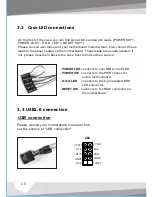
On the front of the case, you can find some LEDs and switch leads (POWER SW*1, 
POWER LED*1, H.D.D. LED*1, RESET SW*1 ). 
Please consult user manual of your motherboard manufacturer, then connect these 
leads to the panel header on the motherboard. These leads are usually labeled; if 
not, please trace them back to the case front to find out their source.

3.2   Case LED connections

3.3 USB2.0  connection

Please consult your motherboard manual to find 
out the section of "

USB connection

".

USB connection

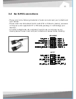
3.4   Ear & MIC connections

11

10

HD AUDIO

A

U

D

IO

10 KEY

8 GND

2 VCC2

4 D2-

6 D2+

D1-3

GND 7

NC  9

D1+5

VCC11

USB 

AC'97

    - 

POWER LED 

connects to your M/B at the PLED.

    - 

POWER SW


connects to the PWR connector 

                               on the motherboard.
    - 

H.D.D LED

     connects to the 2-pin labeled HDD 

                               LED connector.
    - 

RESET SW


connects to the RSW connector on 

                               the motherboard.

- Please refer to the following illustration of Audio connector and your motherboard 
  user manual.
- Please select the motherboard which used AC'97 or HD Audio (Azalia), (be aware 
  of that your audio supports AC'97 or HD Audio (Azalia)) or it will damage your 
  device(s).
- On some motherboards, the connectors for Audio are not the same as the 
  drawing below. Please check with your motherboard manual before installing. 

Summary of Contents for VI1000BNS

Page 1: ...2007 Thermaltake Technology Co Ltd All Rights Reserved www thermaltake com C All other registered trademarks belong to their respective companies ...

Page 2: ...User s Manual ...

Page 3: ...ctions 3 3 USB2 0 connection 3 4 Ear MIC connections Chapter 3 Motherboard Leads Installation 2 6 PCI slot usage 3 1 Motherboard Installation 2 5 HDD installation 2 4 3 5 device installation Chapter 2 Case Mechanical Operation 2 1 How to open the side panel 2 2 How to install PSU 2 3 5 25 device installation 1 2 3 3 4 6 8 9 10 10 11 12 ...

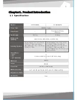
Page 4: ...el Net Weight Case Type 12 x 9 6 ATX 9 6 x 9 6 Micro ATX SECC Black USB x 2 HD Audio Yes Front intake 120 x 120 x 25 m m 1300rpm 17dBA blue LED fan Rear exhaust 120 x 120 x 25 m m 1300rpm 17dBA Front intake 120 x 120 x 25 mm 1300rpm 17dBA blue LED fan Rear exhaust 120 x 120 x 25 mm 1300rpm 17dBA blue LED fan Side intake Two 120 x 120 x 25 mm fans optional 9 1 Converted from one 5 25 drive bay 3 Ma...

Page 5: ...2 1 How to open the side panel 2 1 1 2 2 To remove the side panel please remove upper and bottom thumb screws on the back of the case Pull the side panel to release it Important Notice If the air guide interferes with CPU cooling fan please remove the CPU air guide as shown ...

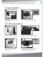
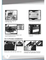
Page 6: ...2 3 3 4 4 2 2 Place power supply unit in the right position Remove the front panel first Remove the 5 25 drive bay mesh cover Remove the 5 25 drive bay metal cover Turn lock device counter clockwise to unlock and remove lock device Then secure it by screws as shown ...

Page 7: ...wise to lock 5 25 device installation complete 2 4 3 5 device installation Remove the 5 25 drive bay mesh cover 5 5 6 6 Insert the device into the 5 25 drive bay Find the proper openings 2 2 Take out the 3 5 mesh bay cover from accessory box then install it as shown ...

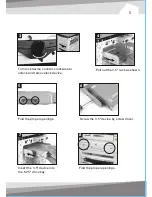
Page 8: ...ce counter clockwise to unlock and remove lock device Pull out the 3 5 rack as shown Screw the 3 5 device by screw driver 5 5 Find the proper openings 7 7 Insert the 3 5 device into the 5 25 drive bay 8 8 Find the proper openings ...

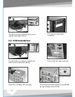
Page 9: ...ock and remove lock device 2 2 Pull out the fan cage as shown Insert the 3 5 HDD into fan cage 10 10 3 5 device installation complete 4 4 Find the proper openings then screw HDD by tigh tening screw to HDD 9 9 Put back the lock device and turn lock device clockwise to lock ...

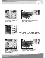
Page 10: ...e back into the drive bays Finish HDD installation 1 1 Note Fan Cage is removable and can be installed in different drive bay Choose another 3 drive bay at desired location for fan cage then insert fan cage into the desired location Put back the lock device and turn lock device clockwise to lock 2 2 ...

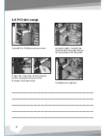
Page 11: ...ip and pull to the right side to lock the Graphic Card as shown Installation complete inner side Take off the PCIbracket as shown Locate Graphic Card to the motherboard through fixing it on the space of PCI bracket 2 6 PCI slot usage 1 1 2 2 ...

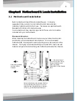
Page 12: ...rd manufacturer On most standard motherboards the edge with external ports goes to the rear part of the chassis It is highly recommended that you install CPU heat sink and modular components before fixing the motherboard inside the chassis 3 1 Motherboard Installation the locations of the screw holes Note these locations and place included standoffs on thechassis first This side towards the rear o...

Page 13: ...se trace them back to the case front to find out their source 3 2 Case LED connections 3 3 USB2 0 connection Please consult your motherboard manual to find out the section of USB connection USB connection 10 10KEY 8GND 2VCC2 4D2 6D2 D1 3 GND7 NC 9 D1 5 VCC11 USB POWER LED connects to your M B at the PLED POWER SW connects to the PWR connector on the motherboard H D D LED connects to the 2 pin labe...

Page 14: ...therboard user manual Please select the motherboard which used AC 97 or HD Audio Azalia be aware of that your audio supports AC 97 or HD Audio Azalia or it will damage your device s On some motherboards the connectors for Audio are not the same as the drawing below Please check with your motherboard manual before installing ...

Page 15: ...e the loading on current PSU and no need to upgrade current PSU while running multi graphic cards mode The functions can assure all Thermaltake Power Supply meets the balance in noise control and heat exhausted All power supply provides complete protection function as follow 1 Over power protection 2 Short circuit protection on all output 3 Over voltage protection Under voltage protection 4 Over c...

Page 16: ...13 ...
Reviews: