SERVICE
30
Manual 0-2583
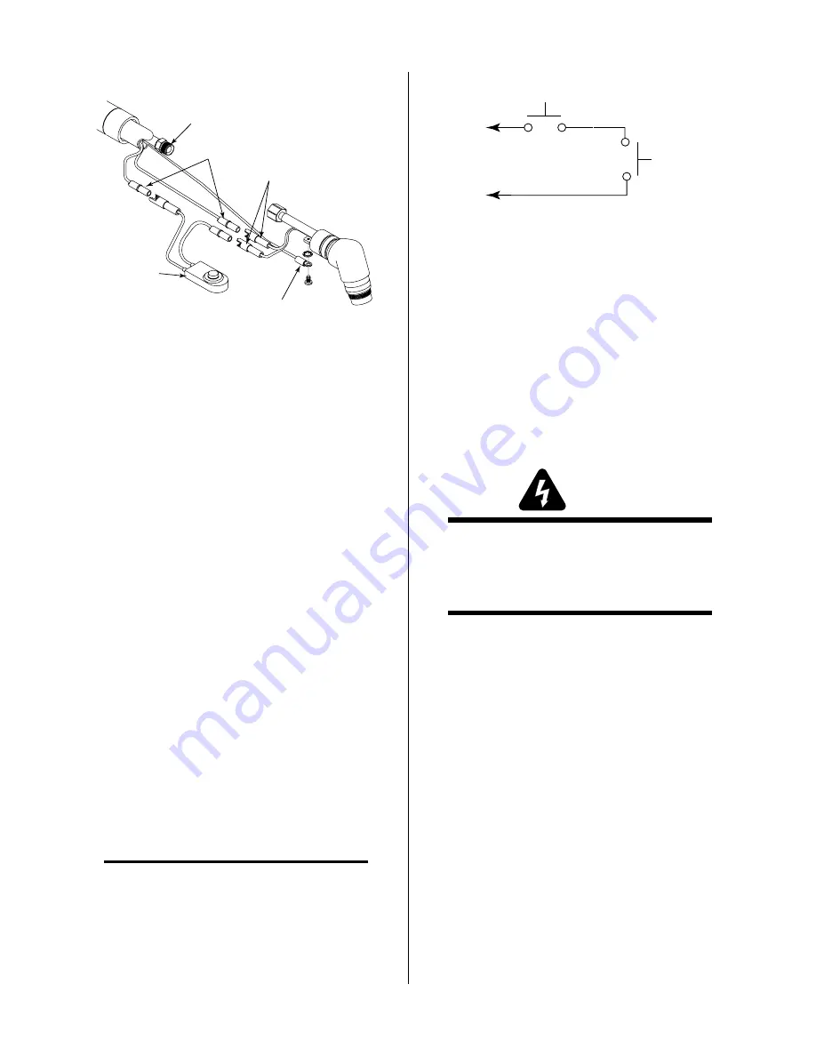
Negative/Plasma
Lead Connection
Pilot Lead
Connection
Parts-In-Place (PIP)
Wires
A-00946
Torch
Switch
Control Cable
Wires
Figure 5-7 Torch Head Removal (PCH-100XL)
10. Disconnect the negative (plasma) lead from the
torch head.
11. Remove the defective torch head assembly.
12. Remove the torch handle and switch from the
leads.
13. If the torch switch is defective, remove the switch
from the torch handle.
B. Installing Torch Switch and Torch Head
Assembly
To install the torch switch or torch head assembly use
the following procedure:
1. Slide the replacement heat shrink tube over the
leads.
2. Slide the torch handle with torch switch and sheath-
ing over the torch leads.
3. Connect the negative (plasma) lead to the replace-
ment torch head assembly.
4. Insert the screw through the pilot control wire lead
lug and then install the star washer before secur-
ing it to the head assembly.
5. Feed the torch switch leads through the handle and
install the torch head on the handle.
NOTE
The torch switch connectors are made to fit into its
matching connector.
6. Connect the two torch switch leads and the PIP
leads to the mating connectors in the leads assem-
bly.
A-00458
Torch Switch
PIP Pin
PIP Pin
Shield Cup
To Control
Cable Wiring
Figure 5-8 Torch Switch and PIP Schematic
7. Tape the two control cable connector leads together.
8. Pull the leads sheathing over the three connectors
and secure with electrical tape to the torch leads.
9. Pull the heat shrink tube back over the connectors
and onto the end of the torch handle tube. Shrink
the tubing into place.
10. Roll the torch switch sheath back over the handle.
5.08 Torch And Leads
Troubleshooting
WARNINGS
Disconnect primary power to the system before
disassembling the torch or torch leads.
DO NOT touch any internal torch parts while the
AC indicator light of the Power Supply is ON.
A. Checking Center Insulator
The center insulator separates the negative and positive
charged sections of the torch. If the center insulator does
not provide adequate resistance, current which is in-
tended for the pilot arc may be dissipated into the torch
head, resulting in torch failure.
1. Remove the shield cup, tip, gas distributor, and
electrode from the torch.
2. Disconnect the torch leads from the power supply
to isolate the torch from power supply circuits.
3. Using an ohmmeter (set to 10K or higher), check
for continuity between the positive and negative
torch fittings.
If infinite resistance (no continuity) is found the
center insulator is okay. Proceed to paragraph B,
Checking Pilot and Switch Control Wires.
If there is continuity between the two torch quick
disconnect fittings proceed to Step 4.
Summary of Contents for PCH-100XL
Page 2: ......
Page 6: ......
Page 18: ...INTRODUCTION DESCRIPTION 12 Manual 0 2583...
Page 22: ...INSTALLATION PROCEDURES 16 Manual 0 2583...
Page 38: ...SERVICE 32 Manual 0 2583...


