OPERATION
22
Manual 0-2583
Workpiece
Rack and
Pinion Mounting
Assembly
Square
A-00934
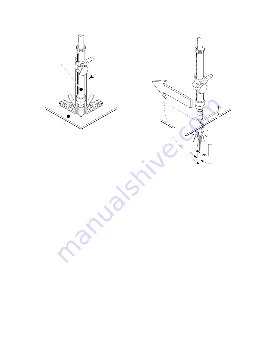
Figure 4-7 Checking Alignment
2. To start a cut at the plate edge, position the center
of the torch along the edge of the plate (refer to
Figure 4-8)
B. Travel Speed
Proper travel speed is indicated by the trail of the arc
which is seen below the plate ( Figure 4-8). The arc
can be one of the following:
1. Straight Arc
A straight arc is perpendicular to the workpiece
surface. This arc is generally recommended for
the best cut using air plasma on stainless or alu-
minum.
2. Leading Arc
The leading arc is directed in the same direction
as torch travel. A five degree leading arc is gener-
ally recommended for air plasma on mild steel.
3. Trailing Arc
The trailing arc is directed in the opposite direc-
tion as torch travel.
Standoff Distance
Straight Arc
Trailing Arc
Leading Arc
Direction of Torch Travel
Shown with
Rack and Pinion
Mounting Assembly
A-01364
Figure 4-8 Machine Torch Operation
For optimum smooth surface quality, the travel speed
should be adjusted so that only the leading edge of
the arc column produces the cut. If the travel speed is
too slow, a rough cut will be produced as the arc moves
from side to side in search of metal for transfer.
Travel speed also affects the bevel angle of a cut. When
cutting in a circle or around a corner, slowing down
the travel speed will result in a squarer cut. The power
source output should be reduced also. Refer to the
approriate Control Module Operating Manual for any
Corner Slowdown (CSD) adjustments that may be
required.
C. Piercing With Machine Torch
To pierce with a machine torch, the arc should be
started with the torch positioned as high as possible
above the plate while allowing the arc to transfer and
pierce. This standoff helps avoid having molten metal
blow back onto the front end of the torch.
When operating with a cutting machine, a pierce or
dwell time is required. Torch travel should not be
enabled until the arc penetrates the bottom of the plate.
As motion begins, torch standoff should be reduced
to the recommended 1/8 - 1/4 inch (3 - 6 mm) dis-
Summary of Contents for PCH-100XL
Page 2: ......
Page 6: ......
Page 18: ...INTRODUCTION DESCRIPTION 12 Manual 0 2583...
Page 22: ...INSTALLATION PROCEDURES 16 Manual 0 2583...
Page 38: ...SERVICE 32 Manual 0 2583...


