background image

Manual 0-2811

3-7

INSTALLATION

A. PCM-102 Torch  Installation

1. Remove the retaining nut from the Strain Relief.

Strain Relief
Nut

Strain Relief

Torch Leads
Assembly

A-02760

Figure 3-10  Torch Strain Relief Nut

2. Feed the end of the torch lead and the Strain Re-

lief into the hole in the unit.

3. Tighten the Strain Relief Nut to secure the Strain

Relief to the Power Supply.

Adapter

(Supplied With
Power Supply)

Pilot Lead

Torch Lead

Assembly

Gas/Power

Lead

Adapter

Connector

Pilot Lead Stud

Gas/Power Lead

Connection

A-02747

PIP Circuit &

Shield Connectors

Figure 3-11  Torch Leads Connections

4. Connect the torch Negative/Plasma Lead to the

bulkhead connection inside the Power Supply.

5. Connect the PIP and Shield Cables to the mating

connectors on the Adapter supplied on the Power
Supply.

6. Remove the top nut and washer from the Pilot

Stud.

7. Place the lug on the Pilot Control Wire onto the

stud and secure with the nut and washer removed
in the above Step.

8. Tighten the Strain Relief onto the Torch Leads.

9. Check the torch for proper parts assembly.

10. Close the access panel and turn the latching screw.

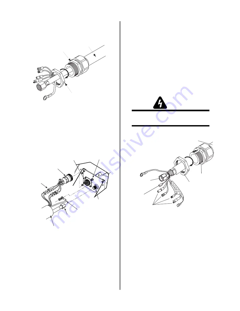
B. SL100 Torch  Installation

Torches with shielded leads and ATC connectors connect
to a shielded ATC Adapter which connects to the power
supply bulkhead.    Torches with shielded leads and O2B
fittings connect directly to the power supply bulkhead.
Bulkhead connections are the same in both applications.

 WARNING

Disconnect primary power at the source before dis-
assembling the torch or torch leads.

Strain Relief

Nut

Strain Relief

Shielded ATC Adapter

Pilot Lead

Negative/Plasma

Lead

Torch Control

Connectors

Shield

Connector

Shield

Connector

A-03677

Strain Relief Nut Removal

1. Remove the Strain Relief Nut from the Strain Re-

lief.  Inside the Power Supply Bulkhead area, route
the connectors on the free end of the Adapter or
Torch Leads through the Strain Relief Nut.

2. Fit the ATC Adapter or Torch Leads end and the

Strain Relief into the hole in the unit.

3. Secure the Strain Relief with the retaining nut re-

moved earlier.

Summary of Contents for CE Pak Master 100XL Plus

Page 1: ...June 26 2003 Manual No 0 2811 Operating Manual Automated Plasma Cutting Power Supply PAK Master 100XL Plus A 02751...

Page 2: ......

Page 3: ...2000 by Thermal Dynamics Corporation All rights reserved Reproduction of this work in whole or in part without written permission of the publisher is prohibited The publisher does not assume and hereb...

Page 4: ...n Features 2 1 2 04 Power Supply Options and Accessories 2 3 SECTION 3 INSTALLATION 3 1 3 01 Introduction 3 1 3 02 Site Selection 3 1 3 03 Unpacking 3 1 3 04 Lifting Options 3 1 3 05 Input Power Conne...

Page 5: ...t 5 6 SECTION 6 PARTS LISTS 6 1 6 01 Introduction 6 1 6 02 Ordering Information 6 1 6 03 Complete Power Supply Replacement 6 2 6 04 Replacement Parts 6 2 6 05 Options and Accessories 6 2 APPENDIX I IN...

Page 6: ......

Page 7: ...your head out of the welding fume plume Use an air supplied respirator if ventilation is not adequate to remove all fumes and gases The kinds of fumes and gases from the plasma arc depend on the kind...

Page 8: ...ns in this manual PLASMAARC RAYS PlasmaArc Rays can injure your eyes and burn your skin The plasma arc process produces very bright ultra violet and infra red light These arc rays will damage your eye...

Page 9: ...able from American National Standards Institute 1430 Broadway New York NY 10018 1 04 Note Attention et Avertissement Dans ce manuel les mots note attention et avertissement sont utilis s pour mettre e...

Page 10: ...er ou m me tuer Le proc d au jet de plasma requiert et produit de l nergie lectrique haute tension Cette nergie lectrique peut produire des chocs graves voire mortels pour l op rateur et les autres pe...

Page 11: ...ue les d cibels le bruit ne d passent pas les niveaux s rs Pour des renseignements sur la mani re de tester le bruit consultez l article 1 page 5 1 06 Documents De Reference Consultez les normes suiva...

Page 12: ...S CURIT POUR LE SOUDAGE ET LA COUPE disponible aupr s de l Association des Normes Canadiennes Stan dards Sales 178 Rexdale Boulevard Rexdale Ontario Canada M9W 1R3 13 Livret NWSA BIBLIOGRAPHIE SUR LA...

Page 13: ...tion standard C22 2 number 60 forArc welding equipment UL Underwriters Laboratory rating 94VO flammability testing for all printed circuit boards used ISO IEC 60974 1 BS 638 PT10 EN 60 974 1 EN50192 E...

Page 14: ...as follows with the exception of XL Plus Series CutMaster Series Cougar and DRAG GUN A maximum of three 3 years from date of sale to an authorized distributor and a maximum of two 2 years from date o...

Page 15: ...supply can be ordered in various con figurations with various options factory installed A 02750 Torch and Leads Work Cable and Ring Terminal Power Supply Figure 2 1 Pak Master 100XL Plus Automated Sys...

Page 16: ...mbly and Two Stage Air Filter installed B Gas Regulator Filter Assembly Specifications The following specifications apply to the Gas Regulator Filter Assembly only 1 Gas regulator maximum gauge pressu...

Page 17: ...es sure for the type gas being used C 575V Transformer This step down transformer allows the power sup ply to operate with 575 VAC three phase input power D Computer Control Cable CNC The interface ca...

Page 18: ...INTRODUCTION 2 4 Manual 0 2811...

Page 19: ...on each side for clearance Provide sufficient clearance in front of the unit to allow access to the front panel controls minimum 6 inches or 0 15 m CAUTION Operation without proper air flow will inhi...

Page 20: ...connections and the input voltage selection WARNING Disconnect primary power at the source before as sembling or disassembling the Power Supply torch parts or torch and leads assemblies 1 Remove the...

Page 21: ...n plug to the desired input connector for 220V 208 230 240V 380 415V or 460V input power operation 3 07 Primary Input Power Cable Connections Units ordered as 230V single phase will have a six foot po...

Page 22: ...0914 L3 L2 Figure 3 6 Single Phase Jumper Wire Installation c Locate the ground stud and remove the top nut and washer d Install a lug terminal on the ground wire e Place the ground wire onto the grou...

Page 23: ...tall the fittings and tighten NOTE Supply hose must be at least 4 hose 1 4 in or 6 mm I D Two Stage Filter Assembly 1 4 NPT to 4 6mm Hose Fitting 4 6mm Gas Supply Hose Hose Clamp A 02744 Figure 3 8 Ga...

Page 24: ...t the gas line to the Regulator Filter As sembly inlet port as shown The illustration shows typical fittings as an example Other fittings may be used Install the fittings and tighten NOTE Supply hose...

Page 25: ...e nut and washer removed in the above Step 8 Tighten the Strain Relief onto the Torch Leads 9 Check the torch for proper parts assembly 10 Close the access panel and turn the latching screw B SL100 To...

Page 26: ...certain amount of electro magnetic interference EMI commonly called RF noise This RF noise may interfere with other electronic equip ment such as CNC controllers remote controls height controllers et...

Page 27: ...may cause more interference than with no shield at all C Creating An Earth Ground 1 To create a solid low resistance earth ground drive a 1 2 in 12 mm or greater diameter copper clad ground rod at lea...

Page 28: ...Logic PC Board SW1 1 2 ON Figure 3 14 SW1 Switch Location WARNING Tip life will be considerably shortened if tip is re peatedly touched to the workpiece without the Tip Saver Drag Sensing Circuit fea...

Page 29: ...ut Location c Locate the internal terminal block TB on the Filter Voltage Divider PC Board located be hind the Logic PC Board The terminal block TB is plugged into a socket on the Filter Volt age Divi...

Page 30: ...when the cut ting arc is on Make sure all connections to the Terminal Block TB are secure f Reinstall the terminal block into the socket on the Filter Voltage Divider PC Board g Secure the CNC cable b...

Page 31: ...l to feed the torch leads through to the internal bulkhead connections 4 Work Cable and Clamp Work cable with ring terminal factory installed for connecting to work table B Control Panel 1 2 3 4 5 6 7...

Page 32: ...rch Panel Connections 2 PIP Shield Connector Connects the torch PIP circuit and shield wires to the unit with an adapter supplied with the Power Sup ply 3 Gas Power Lead Connection Connects the torch...

Page 33: ...block diagram 1 Close main power source disconnect a AC power is available at the Power Supply 2 Place RUN SET LATCH switch to RUN mode 3 Place the ON OFF power switch on the front panel of the Power...

Page 34: ...ion Check the torch for proper assembly and appropriate front end torch parts The torch parts shield cup tip and elec trode must correspond with the type of operation cut ting or gouging B Check Prima...

Page 35: ...surface of the workpiece Excessive dross may require secondary clean up opera tions after cutting Kerf Width The width of material removed during the cut Nitride Build up Nitride deposits which may re...

Page 36: ...OPERATION 4 6 Manual 0 2811...

Page 37: ...ut power cable for damage or exposed wires replace if necessary Weekly or Every 30 Cutting Hours 1 Check fan for proper operation and adequate air flow 2 Vacuum dust and dirt out of the entire machine...

Page 38: ...is assembling the power supply torch or torch leads Frequently review the Important Safety Precau tions page 1 Be sure the operator is equipped with proper gloves clothing eye and ear protection Make...

Page 39: ...edge and can be easily re moved When cutting a troublesome steel it is suggested that the torch travel speed be reduced to produce slow speed dross Any required cleanup can then be done by scrap ping...

Page 40: ...ies Repair as needed being sure to verify that unit is fully operational after any repairs A AC Power indicator OFF 1 Switch at customer s main power panel in OFF posi tion a Close main power panel sw...

Page 41: ...input or output connections a Check all input and output connections 2 Incorrect setting of CURRENT control a Check and adjusted to proper setting 3 Faulty components in unit a Return for repair or ha...

Page 42: ...ect the ground wire 2 Carefully pull the Left Side Panel up and away from the unit to gain access to the inside of the unit 3 To reinstall the left side panel do the following a Place the left side pa...

Page 43: ...TE Parts listed without item numbers are not shown but may be ordered by the catalog number shown B Returns If a product must be returned for service contact your distributor Materials returned withou...

Page 44: ...g 9 7535 1 Two Stage Air Filter Assembly 9 7527 1 Replacement First Stage Filter 9 1021 1 Replacement Second Stage Filter 9 1022 6 05 Options and Accessories Qty Description Catalog 1 Multi Purpose Ca...

Page 45: ...and Canadian Electrical Code NOTES The table above is based on the following output current voltage 140VDC 80A Refer to Local and National Codes or local authority having jurisdiction for proper wirin...

Page 46: ...ain arc will transfer After post flow Gas solenoid closes gas flow stops GAS indicator off ACTION Open external disconnect RESULT No power to system ACTION Close external disconnect switch RESULT Powe...

Page 47: ...Cutting Machine Controller CNC to Plasma Power Supply A 02259 Start Motion OK To Move J22 3 4 10 11 12 14 Red Black Blue Orange White Green Source 15 vdc 10ma Not Used Not Used Cutting Machine CNC Ca...

Page 48: ...e values Second row Rated cutting current values Third row Conventional load voltage values I A 03288 Output Range Amperage Voltage Type of Power Supply Note 1 Output Current Type Rated No Load Voltag...

Page 49: ...Manual 0 2811 A 5 APPENDIX This page left blank...

Page 50: ...APPENDIX A 6 Manual 0 2811 APPENDIX V SYSTEM SCHEMATIC A 02765...

Page 51: ...Manual 0 2811 A 7 APPENDIX A 02765...

Page 52: ......

Reviews: