background image

1

PLEASE READ CAREFULLY:
For a complete list of the pre-delivery service checks performed by your dealer, refer to PRE-DELIVERY SERVICE on the upper portion of page
61 and 63. The copy on page 61 is your record of the service performed, and the copy on page 63, which is to be removed from the manual, is
your dealer’s. MAKE SURE THAT YOU AND THE DEALER SIGN BOTH COPIES.

After you have operated your tractor for fifty hours, take this manual and your tractor to your dealer. He will then perform the factory recommended
50-HOUR SERVICE as listed on the lower portions of pages 61 and 63 - without charge - except for lubricant, oil, or filters replaced as part of
normal maintenance. MAKE SURE THAT YOU AND THE DEALER SIGN BOTH COPIES.

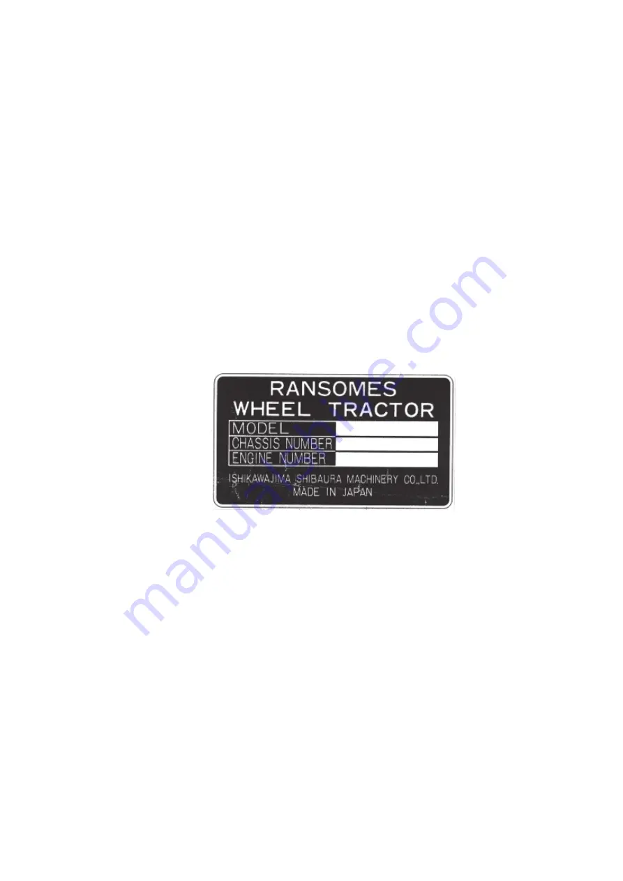
A PRODUCT IDENTIFICATION PLATE is located on the left-hand side of the transmission housing. The numbers on the plate are important
should your tractor require future service. For your convenience, have your dealer record the numbers in the appropriate spaces below.

RANSOMES policy is one of continuous improvement, and the right to change prices, specification or equipment at any time without notice is
reserved.

All data given in this book is subject to production variations. Dimensions and weights are approximate only and the illustrations do not necessarily
show tractors in standard condition. For exact information about any particular tractor please consult your RANSOMES Tractor Dealer.

Summary of Contents for Ransomes CT435

Page 1: ...Ransomes Way Ipswich England IP3 9QG RANSOMES CT435 COMPACT TRACTOR GB OPERATORS INSTRUCTIONS Publication No 24080G rev 1 RSJ 001 101997 ...

Page 2: ......

Page 3: ... lubricant oil or filters replaced as part of normal maintenance MAKE SURE THAT YOU AND THE DEALER SIGN BOTH COPIES A PRODUCT IDENTIFICATION PLATE is located on the left hand side of the transmission housing The numbers on the plate are important should your tractor require future service For your convenience have your dealer record the numbers in the appropriate spaces below RANSOMES policy is on...

Page 4: ...IONS FOUR WHEEL DRIVE AND PTO 15 18 TOWINGTHETRACTOR 18 OPERATING THE DIFFERENTIAL LOCK 18 19 OPERATING THE HYDRAULIC LIFT SYSTEM 19 22 DRIVING THE TRACTOR 22 24 WHEEL TREAD SETTINGS 24 27 TRACTOR WEIGHTING 28 29 TYRE PRESSURES 30 31 LUBRICATION AND MAINTENANCE 32 55 LUBRICATION AND MAINTENANCE CHART 32 33 FUEL AND LUBRICANTS 34 37 FUEL AND LUBRICANT SERVICE PROCEDURES 37 42 GENERAL MAINTENANCE 42...

Page 5: ...ously variable Increase Decrease Fuel level Creeper range High range Middle range Low range Neutral Diesel fuel Glow Engine stop Engine oil Parking brake Lights upper beam Lights lower beam Lock Release lock Up Down Differential lock Read operator s manual Battery Power take off on Power take off off Tortoise slow or minimum setting Hare fast or maximum setting Warning Control lever operating dire...

Page 6: ...ocks in place Pulling from the tractor rear axle or any point above the axle may cause the tractor to upset SAFETY PRECAUTIONS The following precautions are suggested to help prevent accidents Acareful operator is the best operator Most accidents can be avoided by observing certain precautions Read and take the following precautions before operating this tractor to help prevent accidents Equipment...

Page 7: ...clean adjust unclog or service P T O driven equipment when the tractor engine is running 5 Make sure the P T O master shield is installed at all times and always replace the P T O shield cap when the P T O is not in use DIESEL FUEL 1 Under no circumstances should gasoline alcohol or blended fuels be added to diesel fuel These combinations can create an increased fire or explosive hazard Such blend...

Page 8: ...l equipment for this tractor at time of factory assembly If the ROPS was deleted by the original purchaser or has been removed it is recommended that you equip your tractor with a Roll Over Protective Structure ROPS ROPS are effective in reducing injuries during tractor over turn accidents Overturning tractor without a ROPS can result in serious injury or death Roll Over Protective Structure ROPS ...

Page 9: ...4th position Headlights High Beam and Tail Lamp ON Figure 4 Light Switch INSTRUMENT PANEL KEY SWITCH The key switch is shown in Figure 5 Turning the key to the left will activate the cold start aid Turning the key to the right to the on position will activate the warning lights and instruments Turning mg the key further right to the start position will start the engine Upon release the key will sp...

Page 10: ...egularly check the crankcase for proper oil level Charge indicator warning light This is an indication that the charging system is not operating normally Investigate the cause as soon as possible otherwise the battery will become fully discharged The glow plug indicator warning light This light comes on when turning the key switch to the HEAT position and START position Refer to page 14 for starti...

Page 11: ...UGE The engine coolant temperature gauge is shown in Figure 6 When the needle is in the middle area the engine is at its normal operating temperature The needle at the red end indicates an overheated engine WARNING When engine is at operating temperature always relieve pressure in the cooling system before removing the radiator cap THROTTLE CONTROLS HAND THROTTLE AND ENGINE STOP CONTROL The hand t...

Page 12: ...r is used on the highway PARKING BRAKE A convntional handbrake lever coupled to the footbrake linkage is installed to the left of the drivers seat To apply the handbrake pull the lever up To release ease the lever up further depress the button on the end and lower the lever Figure 13 IMPORTANT Ensure the handbrake is fully released before driving off DIFFERENTIAL CONTROL DIFFERENTIAL LOCK PEDAL Th...

Page 13: ...2 reverse speeds CREEPER RANGE ACCESSORY A creeper range accessory with a 1 2 29 1 ratio is available which provides an additional 1 2 forward and 4 reverse speeds or a total of 24 forward and 8 reverse speeds The creeper range accessory of synchromesh transmission provides an additional 1 2 forward and 1 2 reverse speeds or a total of 24 forward and 24 reverse speeds The control is located on the...

Page 14: ... operation during uses such as loader operation that do not require use of the P T 0 system WARNING The P T 0 system cannot be disengaged with the alternate clutch pedal stop DO NOT engage the alternate STOP with the P T 0 control lever in the on position Never attempt to operate P T 0 driven equipment with the alternate stop engaged TRANSMISSION P T 0 CONTROL LEVER The transmission P T 0 control ...

Page 15: ...lever is position control lever the inner lever is the draft control lever The position control lever is used to raise or lower the hydraulic lift arms To raise the lift arms pull the lever upward To lower the lift arms push the lever downward The adjustable stop is provided for locating the lever at any position in the quadrant The draft control lever is used to adjust sensitivity to draft loads ...

Page 16: ... starting the engine WARNING Never attempt to start the engine while standing beside the tractor always sit in the seat when starting the engine IMPORTANT Do not engage the starting motor continuously for more than 30 seconds doing so may cause starting motor failure WARM WEATHER STARTING To start a cold engine in warm weather or to start an engine that is warm 1 Depress the clutch pedal fully and...

Page 17: ...procedure above This will help protect the alternator from damage due to extreme load changes WARNING Batteries contain sulphuric acid and produce explosive gases Follow the instructions below to prevent personal injury Wear eye and skin protection Keep sparks and flame away Always have adequate ventilation while charging or using the battery Follow the battery manufacturer s instructions which ar...

Page 18: ...ward for travel forward pull rearward for travel rearward Always depress the clutch pedal fully before changing the shuttle lever position The main shift lever has 4 positions to select the required transmission range Any of main gear ratios may be selected with the tractor moving or stationary provided the clutch pedal is depressed The range selector lever has 3 positions to select the required t...

Page 19: ...AKE OFF The power take off P T 0 in your tractor transfers engine power directly to mounted or pull type P T 0 equipment The standard P T 0 speed is 540 10 rpm Most P T 0 equipment is designed to operate efficiently at this speed This speed is obtained when engine rpm is set at 2238 rpm as indicated by the P T 0 symbol on the Proof Meter rpm scale IMPORTANT Do not exceed 2238 rpm engine speed when...

Page 20: ...t the P T 0 and tractor in motion 6 Control the P T 0 speed with the throttle never exceeding 2238 rpm or the speeds shown in the following table If the tractor movement is too fast for the P T 0 load stop the tractor and shift transmission to a lower gear 7 Disengage the P T 0 with the P T 0 control lever when making sharp turns with pull type equipment and with mounted equipment in the fully rai...

Page 21: ...speed than the other Should this happen the lock may be disengaged by either of two ways Decrease the drawbar pull by raising or disengaging the implement so that neither wheel tends to slip OR Rapidly apply and release a light braking load to the slipping rear wheel OPERATING THE HYDRAULIC LIFT SYSTEM SINGLE LEVER HYDRAULIC LIFT SYSTEM STANDARD The hydraulic lift system provides accurate smooth a...

Page 22: ...e tends to rotate the equipment upward around the lower link hitch points This draft creates a pushing or compression force on the upper link When changes in soil resistance cause the draft to increase the compression force on the upper link will also increase or decrease These changes in upper link compression signal the hydraulic system through internal linkage to raise or lower the equipment to...

Page 23: ...valve Figure 31 provides an adjustment to regulate the flow of oil from the lift cylinder thus slowing or increasing the rate of drop of the lower links To adjust rate of flow either turn the flow control valve IN clockwise to decrease the rate of drop or OUT counterclockwise to increase the rate of drop The flow control valve must be opened before hydraulic lift control will function Figure 31 Ro...

Page 24: ...3 Hydraulic Manifold Block To operate auxiliary equipment remove the plugs from the manifold block and connect the feed hose to the outlet port Figure 33 and the return hose to the inlet port IMPORTANT In order to operate auxiliary equipment the control screw must be turned to the position at 2 With a front remote valve installed it is not required to turn the control screw to the position shown a...

Page 25: ...t Do not exceed 10 M p h 16 K p h if towed equipment weighs more than the tractor Do not exceed 20 M p h 32 K p h while towing equipment that weighs less than the tractor SWINGING DRAWBAR where fitted The swinging drawbar may be fixed or allowed to swing the full width of the hanger Fasten the drawbar in position using the swing limiter pins when pulling equipment which requires accurate positioni...

Page 26: ...nd grade chain strength washers lockwasher nuts etc After attaching the safety chain make a trial run by driving the tractor to the right and to the left for a short distance to check the safety chain adjustment If necessary readjust to eliminate tight or loose chain Safety chains and suitable hardware are available from your RANSOMES Tractor dealer WHEEL TREAD SETTINGS FRONT WHEEL TREAD SETTINGS ...

Page 27: ... 134 5cm REAR WHEEL TREAD SETTINGS Cont d The optional 76 inch rear axle is adjustable from 52 4 to 76 inch 133 to 193cm Tread width settings are made by changing the position of the wheel discs and the rims and by interchanging the rims from side to side These various positions are shown in Figure 36 and 37 NOTE After changing the rear wheel tread setting the wheel rim to disc nuts and the disc t...

Page 28: ...n Disc 3 Inter Changing Rear Wheel Assemblies 2 Rim Repositioned On Opposite Disc Give These Combinations Figure 37 Rear Wheel Tread Settings Optional 76 Inch Axle 1 Reposition Rim On Disc 3 Inter Changing Rear Wheel Assemblies 2 Rim Repositioned On Opposite Disc Give These Combinations ...

Page 29: ...7 OPERATION Figure 37 Rear Wheel Tread Settings Optional 76 Inch Axle Continued 1 Reposition Rim On Disc 3 Inter Changing Rear Wheel Assemblies 2 Rim Repositioned On Opposite Disc Give These Combinations ...

Page 30: ...igh speed on rough terrain Reduce tractor speed and exercise caution under these conditions When using front mounted equipment add weight to the rear axle to maintain good traction and stability WARNING If proper stability cannot be obtained within the weighting limitations below reduce the load on the tractor until stability is obtained IMPORTANT Do not exceed the tire load and inflation specific...

Page 31: ...29 OPERATION Figure 39 Rear Wheel Weights Figure 40 Front End Weights ...

Page 32: ...service and or mount tires when possible In any event to avoid possible serious or fatal injury follow the safety precautions below Be sure the rim is clean and free of rust Lubricate both tire beads and rim flanges with soap solution Do not use oil or grease Use a clip on tire chuck with a remote hose and gauge which allows the operator to stand clear of the tire while inflating it NEVER INFLATE ...

Page 33: ...E L B I S S I M R E P M U M I X A M s b l 0 5 4 0 1 5 0 7 5 0 2 6 0 7 6 0 8 7 g k 4 0 2 1 3 2 9 5 2 1 8 2 4 0 3 4 5 3 s b l 5 1 7 0 7 7 0 4 8 0 7 9 5 4 0 1 g k 5 2 3 0 5 3 0 8 3 0 4 4 5 7 4 s b l 5 7 7 5 8 8 5 8 9 5 2 3 1 g k 0 5 3 2 0 4 7 4 4 1 0 6 E R U S S E R P N O I T A L F N I E Z I S E R Y T R A E R i s p 2 1 4 1 6 1 8 1 0 2 2 2 4 2 6 2 r a b 3 8 0 6 9 0 1 1 2 1 4 1 5 1 7 1 8 1 1 R r p 4 4 ...

Page 34: ...32 LUBRICATION AND MAINTENANCE LUBRICATION AND MAINTENANCE CHART RANSOMES CT325 CT333 TWO WHEEL DRIVE ...

Page 35: ... 1 e g a k n i L t n i o P 3 X 7 r e d n i l y C g n i r e e t S r e w o P X 1 1 t f a h S l a d e P X 0 1 l a d e P e k a r B X 2 2 t f a h S t o v i P X 6 1 l a d e P h c t u l C X O N D N A N O I T A C I R B U L E C N A N E T N I A M S M E T I C H E C K C L E A N L U B E C H A N G E A D J U S T E C I V R E S S L A V R E T N I 7 1 l i O e n i g n E X y r e v E s r u o H 0 0 1 8 t n e m e l E r e...

Page 36: ... to reduce costs and conserve energy Today s new fuels or blends are frequently more volatile and there is a need to handle them carefully Furthermore some of the blends are dangerous and should not be used at all The following new or blended fuels are becoming available or are sometimes recommended by certain sources Our recommendations are as follows Diesel Under no circumstances should gasoline...

Page 37: ...ain medical attention immediately or gangrene may result Failure to follow these instructions can result in serious injury FUEL STORAGE Extremely small clearances exist between the fuel delivering elements of the fuel injection pump and the fuel delivering elements of the injectors Therefore it is of vital importance that precautions be taken to make sure the fuel is kept free of dirt and water Fi...

Page 38: ...bricant to use Transmission Rear Axle Final Reduction Hydraulic System SAE 80 Power Steering Oil ISO VG32 Front Axle Oil SAE 80 Engine Crankcase Service Grade CD SAE 10W30 for year around use or SAE 20W for use 5 C 25 C SAE 30 for use 1O C 35 C Front Wheel Bearings and All Lubrication Fittings NLG I GRADE 2 EP GREASE WITH LITHIUM SOAP NOTE Use the following chart to determine which SAE Grade engin...

Page 39: ...actor standing level and after the engine has been stopped for a period of time check the oil level with the dipstick Figure 43 Figure 43 Engine Oil Level Dipstick and Filter 2 lf the oil level is low remove the filler cap Figure 44 and add oil to the engine through the filler hole to bring the oil level between the marks on the dipstick Be careful not to overfill 3 Install the oil filler cap Figu...

Page 40: ... the oil is at the proper level FUEL FILTER Draining the Filter Drain the diesel fuel filter when water is visible in the sediment bowl Cleaning the Fuel Filter Clean the fuel filter every 100 hours by rinsing in a container of clean diesel fuel 1 Be sure there is adequate fuel in the fuel tank close the fuel shut off valve then remove the fuel sediment bowl Figure 46 Figure 46 Fuel Filter and Fue...

Page 41: ... been installed or if the injection pump has been removed for service repairs 1 Loosen the injector line fittings at the injectors 2 Move the hand throttle control lever to its wide open position 3 Crank the engine until air free fuel flows from each connection then tighten the fittings to 18 22 lbs ft 24 29 Nm IMPORTANT Do not crank the engine continuously for more than 30 seconds Doing so may ca...

Page 42: ...a wet element as the tractor engine will not start with a wet element installed 4 After drying check for damage by holding a light bulb inside the element If an even fine pattern of light is seen the element is clean and undamaged A bright spot of light indicates the element is damaged and a new element must be installed Change the element after six cleanings or once a year TRANSMISSION REAR AXLE ...

Page 43: ...tick as the oil reservoir will be overfilled 3 Install the dipstick filler plug Figure 51 Power Steering oil Level Dipstick Filler Plug and Drain Plug Changing Oil Change the oil every 600 hours 1 With the oil at normal operating temperature drain the oil by removing the drain plug of reservoir for power steering Figure 51 Reinstall the plug after the oil has drained Discard the oil 2 Remove the f...

Page 44: ...AINTENANCE COOLING SYSTEM The cooling system in your RANSOMES Tractor has been filled with one year lift antifreeze To obtain maximum efficiency and service life from the engine it must operate at the correct temperature This is dependent on the cooling system The system should be kept filled with a 50 50 solution of permanent antifreeze and clear water Checking Coolant Level Check the coolant lev...

Page 45: ...nd run water through the system with the engine running Figure 54 Combination Engine Block and Radiator Drain Valve Make sure water is flowing from the drain valve before starting the engine When the water flowing from the drain valve is free of discoloration and sediment stop the engine and remove the hose Allow all water to drain from the system through drain valves 3 Close the drain valve and s...

Page 46: ... belt is too tight it will shorten the alternator bearing life A correctly tightened belt will deflect 7 1 6 to 9 1 6 inch 10 to 15 mm when 20 to 25 pounds 9 to 11 kg thumb pressure is applied midway between the belt pulleys Check the condition and tension of the fan belt every 200 hours If the belt shows signs of cracking or fraying install a new belt To Adjust Belt Tension 1 Loosen the alternato...

Page 47: ... Line 2 Install the injector lines Finger tighten the fittings at the injectors until after bleeding the fuel system Tighten the fittings at the injection pump and injectors to 58 61 lbs ft 78 83 N m 3 Install the leak off line Tighten the leak off line nuts to 22 36 lbs ft 29 41 N m 4 Bleed the fuel system as covered under Bleeding the Fuel System page 39 Tighten the injector fittings ENGINE SPEE...

Page 48: ... Tighten the cover bolts evenly Figure 60 Checking Valve Clearance MAINTENANCE AND INSPECTION OF THE ROPS After the first 20 hours of operation and after every 500 hours of operation or six months whichever comes first do the following 1 Check the torque of the ROPS mounting bolts If necessary tighten the bolts to the correct torque See bolt torques page 58 2 Check the operators seat Replace parts...

Page 49: ...yte Checking Electrolyte Level Check the electrolyte level in the battery every 50 hours WARNING When the alternator is charging an explosive gas is produced inside the battery Therefore always check the electrolyte level with the engine stopped Do not use an exposed flame and do not smoke when checking the battery electrolyte level 1 Clean the top of the battery then remove the vent plugs 2 If th...

Page 50: ...tor warning light indicates that the alternator is not charging the battery check the fan belt and the wiring connections If these are satisfactory and the warning light continues to indicate no charge consult your RANSOMES Tractor Dealer FUSE BOX The fuse box is shown in Figure 62 The plastic fuse cover is easily removed by pulling it off Always replace blown fuses with the specified fuse Figure ...

Page 51: ... possible In any event to avoid possible serious or fatal injury follow the safety precautions below Be sure the rim is clean and free of rust Lubricate both tire beads and rim flanges with soap solution Do not use oil or grease Use a clip on tire chuck with a remote hose and gauge which allows the operator to stand clear of the tire while inflating it NEVER INFLATE TO OVER 35 psi 2 4 bar TO SEAT ...

Page 52: ...tires at wheel hub height Figure 66 2 Measure and record the distance between the front of the wheels at the marks then push the tractor forward or backward until marks are at wheel hub height on the rear of the wheel 3 Measure and record the distance between the marks at the rear of the wheels 4 The difference between the dimensions recorded in Step 2 and 3 should give zero to 13 64 inch 0 5 mm t...

Page 53: ...rake Adjustment If the parking brake lever travel becomes excessive or the parking brake efficiency is reduced adjust the parking brake as follows 1 Check and if necessary adjust the foot brakes as previously described 2 Release the parking brake lever Figure 67A Slacken the locknut and turn the adjusting nut so that both rear wheels are locked when the parking brake lever is applied 3 4 notches o...

Page 54: ... To ensure correct steering operation the stop bolt Figure 69 should protrude a minimum of 1 1 in 28 mm from the casing Changing Oil Change the oil every 300 hours 1 With the oil at normal operating temperature drain the oil by removing the front axle differential Figure 70 and final reduction gear case drain plugs Figure 71 Reinstall the plugs after the oil has drained Discard the oil 2 Remove th...

Page 55: ...he transmission hydraulic system and rear axle with new oil Drain the engine oil and refill with new lubricating oil Also clean the air cleaner 5 If the tractor is stored or removed from operation for an extended period special precautions should be taken to protect the fuel injection pump and the injector nozzles against corrosion and gumming during the storage period Before storing the fuel syst...

Page 56: ...en clutch pedal and step plate to separate clutch disc from flywheel Figure 72 Figure 72 Installing Pedal spacer Tractors that have been placed in storage should be completely serviced in the following manner before using 1 Inflate the Tyres to the recommended pressures and remove the blocking 2 Check the oil level in the engine crankcase power steering reservoir the common sump for the hydraulic ...

Page 57: ...55 METRIC BOLT TORQUE SPECIFICATIONS LUBRICATION AND MAINTENANCE ...

Page 58: ...n and specifications at any time without notice and without obligation to modify units previously built Properly Maintained Equipment is Safe Equipment The specifications on the following pages are provided for your information For additional information see your RANSOMES Tractor Dealer SPECIFICATIONS ...

Page 59: ...n X 5 6 in Diameter 17 5 cm X 14 3 cm STEERING Type Hydrostatic Turns Lock to Lock 3 8 Front Wheel Toe In 0 13 64 in 0 5 mm ENGINE Type Diesel Number of Cylinders 4 Bore 3 31 in 8 4cm Stroke 3 54 in 9 0cm Displacement 121 75 cu in 1995 cc Compression Ratio 1 9 1 Firing Order 1 3 4 2 Low Idle Speed 900 1000 rpm Maximum Speed High Idle 2650 2700 rpm Rated 2500 rpm Valve Clearance Cold Engine Intake ...

Page 60: ...T TOROUES Front Wheel Disc to Hub 137 159 lbs ft 186 215 N m Rear Wheel Disc to Rim 137 159 lbs ft 186 215N m Rear Wheel Disc to Axle 137 1 59 lbs ft 186 215 N m ROPS ATTACHING BOLT TOROUES ROPS to Fender Mount Ml 2 55 lbs ft 74 N m CAST IRON WEIGHTS 5 Front End Weights 33 lbs 15kg each 4 Rear Wheel Weights 66 lbs 30 kq each Draw Bar Swinging Standard LUBRICANTS NOTE Should the recommended engine ...

Page 61: ...09 0 cm Adjustable 116 155 cm Width 64 0 in Weight W ROPS 3020lbs 162 5 cm Less Options 1370kg LUBRICANTS Cont d TRACTOR COMPONENT LUBRICANT RECOMMENDATION Type of lubricant to use Transmission Rear Axle Final Reduction and Hydraulic System Oil SAE 80 Power Steering Oil ISO VG 32 Front Axle Oil SAE 80 Engine Crankcase Service Grade CD SAE 1 0W30 for year around use or SAE 20W for use 5 C 25 C SAE ...

Page 62: ...60 SPECIFICATIONS ...

Page 63: ... they should be replaced with new decals at their original position Replacement decals are available from your RANSOMES Tractor Dealer CAUTION Battery PART NO SBA 390193110 LOCATION Inside of front hood CAUTION PTO cap PART NO SBA 390193070 LOCATION On the master shield ...

Page 64: ...MP START PART NO SBA 490990571 LOCATION Inside of hood WARNING Keep hands and clothing away from rotating fan PART NO SBA 390191352 LOCATION Rear of radiator WARNING Caution for road running PART NO SBA 3901g3210 LOCATION L H fender ...

Page 65: ...ION Left below seat right of control Creeper Range Lever PART NO SBA 390170680 LOCATION Right of creeper lever left side of platform Range Selector Lever S S S PART NO SBA 390171970 LOCATION Left of seat to the right of range quadrant Four Wheel Drive Control Lever PART NO SBA 390170630 LOCATION Below and to right front of seat next to control lever Range Selector Lever PART NO SBA 390172040 LOCAT...

Page 66: ... that are to be stored PART NO SBA 390194690 LOCATION On plastic block Installing pedal spacer PARTNO SBA 390194700 LOCATION On plastic block Starter Switch PART NO SBA 390194290 LOCATION Starter Switch right side of instrument panel Multi P T O control lever PART NO SBA 390172280 LOCATION Left of seat on quadrant Multi P T O control lever PART NO SBA 390172290 LOCATION Left of seat on quadrant ...

Page 67: ...N Top of flow control knob Draft control lever PART NO SBA 390371300 LOCATION Right of seat to the rear of draft quadrant lever Hydraulic Power Take off PART NO SBA 390193830 LOCATION On the floor Postion control lever PART NO SBA 390371320 LOCATION Inside of R H fender ...

Page 68: ...66 INSTRUCTION DECALS Lubrication and Maintenance Intervals PART NO SBA 390194380 LOCATION On inside of hood Power Steering Fluid PART NO SBA 390230130 LOCATION Top of P S reservoir ...

Page 69: ...67 INSTRUCTION DECALS Ground speed diagram 12x4 PART NO SBA 390172020 LOCATION Top of LH fender Ground speed diagram 555 PART NO SBA 390172030 LOCATION Top of LH fender ...

Page 70: ...68 NOTES ...

Page 71: ...lic System Selector lever for position control Flow control operation 6 4 wheel drive lever operation 7 Low speed creeper lever 8 Operation of H S T TRACTOR MODEL NO TRACTOR SERIAL NO INSPECTION PERFORMED OWNER S SIGNATURE DATE DEALER S Signature DATE INOPERATIVE SERVICE CHECKS 1 Tire pressure 2 check air cleaner hose connection 3 Replace diesel fuel filter s 4 Tighten in line pump delivery valve ...

Page 72: ...70 ...

Page 73: ...lic System Selector lever for position control Flow control operation 6 4 wheel drive lever operation 7 Low speed creeper lever 8 Operation of H S T TRACTOR MODEL NO TRACTOR SERIAL NO INSPECTION PERFORMED OWNER S SIGNATURE DATE DEALER S Signature DATE INOPERATIVE SERVICE CHECKS 1 Tire pressure 2 check air cleaner hose connection 3 Replace diesel fuel filter s 4 Tighten in line pump delivery valve ...

Page 74: ......

Page 75: ......

Page 76: ...Ransomes Way Ipswich England IP3 9QG RANSOMES ...

Reviews: