Texmate, Inc. Tel. (760) 598-9899 • www.texmate.com
FL-B101Q-HZ_manual (d0059)
Page 7
Setpoint Adjust
The bargraph has the option to have up to 4 setpoints (two 9A Form C relays and two 4A Form A relays) installed. Each relay may
be set to activate either above or below its setpoint by inserting jumper clips on the Relay Activation header which is located on the
Display Driver Board. See the layout diagram on Page 4 for the exact location. The steps to setup the setpoints are as follows:
1) SELECT THE RELAY ACTIVATION MODE FOR EACH INSTALLED RELAY
Make sure that the required relays have been installed in the meter. Refer to the component layout on Page 11 for relay posi-
tions. If a jumper clip is installed in a specific relay position on the Relay Activation Mode Header, that relay will activate when
the display bar is lower that the programmed setpoint. If no jumper clip is installed in a specific relay position on the Relay
Activation Mode Header, that relay will activate when the display bar is equal to or higher that the programmed setpoint. The
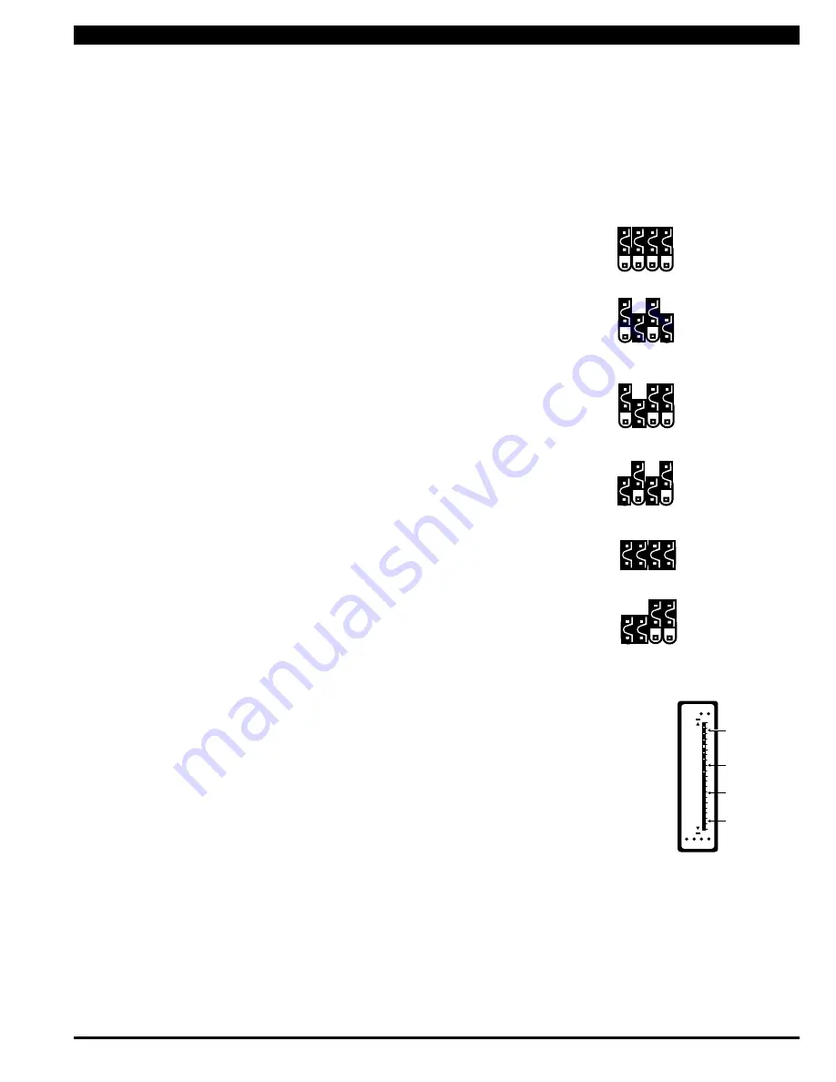
Diagrams below show some of the various possibilities for relay activation.
Default
SP1, SP2, SP3, and SP4 all activate when input is equal to or higher than set point.
SP2 and SP4 activate when input is lower than set point. SP1 and SP3 activate when input
is equal to or higher than set point.
SP2 activate when input is lower than set point. SP1, SP3 and SP4 activate when input is
equal to or higher than set point.
1
3 4
2
sP
1
3 4
2
sP
1
3 4
2
sP
SP1 and SP3 activate when input is lower than set point. SP2 and SP4 activate when input
is equal to or higher than set point.
SP1, SP2, SP3, and SP4 all activate when input is lower than set point.
1
3 4
2
sP
SP1 and SP2 activate when input is lower than set point. SP3 and SP4 activate when input
is equal to or higher than set point.
1
3 4
2
sP
1
3 4
2
sP
100
0
25
50
75
SP1 SP2 SP3 SP4
Zero Span
SP2
SP1
SP3
SP4
2) ADJuST THE SETPOINT FOR EACH RELAY
The setpoint for each relay is set by the front panel buttons marked SP1, SP2, SP3 and
SP4. When a front panel button is pressed and held down, the associated setpoint is directly
changed. The direction of change will be either up or down, as indicated by the UP and DOWN
indicator LEDs. After the indicator LED lights up there is a 0.5 second delay before any change
occurs. To reverse the direction of change, release the button and then press down again. As
there are no menus or sub-menus to navigate, the programming and setup is quick and easy.
Setpoints are indicated on the bar display by an ON segment if the bar is below the setpoint
and with an OFF segment if the bar display is above the setpoint.


