


Texmate, Inc. Tel. (760) 598-9899
•
www.texmate.com
Page 6
6/23/04 DI-50B51 320 Series (NZ306)
P
l
a
nn
i
n
g
t
o
H
a
r
n
e
ss
t
h
e
P
o
w
e
r
o
f
T
i
g
e
r
320 P
r
og
r
a
mm
a
b
l
e
M
e
t
e
r
C
o
n
t
r
oll
e
r
s
A combination of modular hardware and software resources
enable Tiger 320 Series Programmable Meter Controllers
(PMCs) to be easily configured as a cost effective solution for
the most simple or the most complex of applications.
A review of your Project
’
s objectives, its physical layout, the
proposed sensors and control outputs will enable you to select
the optimum configuration of the Tiger 320 PMC
’
s unique hard-
ware and software capabilities.
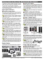
Input Signals & Sensors
4-20 mA or Sensor Direct
Unless sensors are located at a far distance, the greatest
accuracy and best performance is usually obtained by
connecting sensors directly to the Tiger 320, which will then
function as the primary measurement device.
There are more than 120 Tiger compatible input signal
conditioning modules, with the appropriate excitation
outputs, to suit almost any type of sensor or combina-
tions of up to 4 sensors.
In most cases, sensors with a 4-20 mA output are more costly,
and when a separate 4-20 mA transmitter is used, signal con-
version, drift, and calibration inaccuracies are introduced.
Some Tiger input modules combine direct sensor inputs
with 4-20 mA inputs, enabling both local and far distant
sensor inputs to be combined.
Sensor Linearization or Compensation
The performance of many sensors can be greatly
enhanced or expanded with linearization and or compen-
sation. Sensors may be compensated for temperature, fre-
quency, altitude, humidity and mechanical position, to name
just a few parameters.
Tiger PMCs with 32 kilobits or more of memory provide
up to four 32-point user defined linearization tables or
one combined 125-point table.
Many compensation methods can be implemented with
the standard cross channel math capabilities of the
Tiger
’
s 32-bit operating system. Complex three-dimen-
sional compensation can also be implemented using the pow-
erful macro programming capability.
The serial number and calibration date of a sensor can
be loaded into the meter. The serial number, lineariza-
tion tables, and compensation factors of a newly cali-
brated sensor can then be saved for future reloading, either
serially through a PC or directly through the web via an
Ethernet port.
Although there are numerous input modules with com-
binations of various input signals, some inputs such as
watts or pH are provided on input modules dedicated to
a single function. Combining these inputs with each other sig-
nals two or more Tiger meters can serially communicate, and
be configured to share their data and processing resources.
DECISION
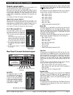
Push Button or Membrane Touch Pads
Tiger PMCs are shipped as standard with high usage hard
plastic push buttons. An optional clear lens cover that
opens on a cam hinge with a key lock can provide full NEMA 4
or IP65 dust and water proofing. Alternatively, an optional mem-
brane touch pad faceplate can be ordered.
Faceplates can be cus-
tomized to suit any
OEM application, and
be quickly produced in large or
small quantities for push but-
tons or membrane touch pads.
Control Outputs & I/O Logic
Electromechanical Relays or Solid
State Control Outputs
Tiger PMCs have a wide selection of control outputs to
chose from. The decision on which control output to choose
depends on the current and the switching frequency.
Electromechanical relays are a popular choice for most control
outputs. Tiger output modules are available with combinations
of two 10 amp form C and two to six 5 amp form A relays that
can be used to directly drive fractional HP motors or actuators.
The limitation of electromechanical relays is switching
speed. If a relay needs to operate in less than 30 mS, or
be cycled faster than .5 cpm, it is advisable to select an
output module with solid state relays (SSR) or open collector
outputs (OC), that can drive external high current SSRs.
tare
SP1 SP2 SP3 SP4 SP5 SP6
Prog.
tare
SP1 SP2 SP3 SP4 SP5 SP6
Prog.
SP
6
5
4
3
2
1
80
100
60
40
20
0
SP
6
5
4
3
2
1
80
100
60
40
20
0
Stack mounting
for greater display
options
Twin or triple mount-
ing for greater display
options
PLANN
ING
TIP
PLANN
ING
TIP
DECISION
PLANN
ING
TIP
PLANN
ING
TIP
PLANN
ING
TIP
PLANN
ING
TIP
LED or LCD Displays
LED displays are a lower cost and popular display option.
They operate over the largest temperature range, have
better viewing angles and viewing distances, and have the
longest operational life. However, red LEDs are difficult to read
in direct sunlight without a shade hood and consume more
power. Green LEDs and backlit LCD displays can be more eas-
ily read in direct sunlight.
The Tiger range can be ordered with red or green LEDs.
LCD displays are also available, with or without back-
lighting.
Numeric or Alphanumeric Displays
Generally, numeric displays are a lower cost option than
alphanumeric displays. The Tiger range supports a full 7-
segment numeric and 14-segment alphanumeric alphabet of
English letters and Arabic numerals. Where complex text mes-
saging or alarm annunciation is required, we recommend
using the 14-segment alphanumeric option.
Single or Multiple Display
The Tiger meter has four input channels and can be con-
figured to display many different inputs or results. These
can be viewed constantly on the operational display, or on
demand in one of the view modes by pressing a button. Some
applications require multiple values to be displayed simultane-
ously. With single, dual, or triple displays, and single displays
with 51 or 101-segment bargraph combinations, we have a
large range of display options to choose from.
Tiger meters can communicate with each other to share
their data and processing resources and be stack or twin
mounted to provide a wider range of display options.
DECISION
DECISION
DECISION
PLANN
ING
TIP
PLANN
ING
TIP
PLANN
ING
TIP
DECISION
PLANN
ING
TIP
TIME
TEMP
No OF LABELS
100
80
90
70
60
50
40
30
20
10
0
SP
1
2
3
4
5
6
P
DECISION
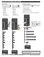
Display Options
6-wire Display
Connector
96x48 mm
Short Depth Case
Remote
Display PCB
96x48 mm
Case
Tiger PMCs have a large range of display options, including dig-
ital and alphanumeric LCDs, LEDs and Touch Panel HMIs.
4
”
7-Segment Remote
Short Depth Remote Display
5.7
”
& 10.4
”
HMIs
Color or Monocolor


