


Texmate, Inc. Tel. (760) 598-9899
•
www.texmate.com
Page 38
6/23/04 DI-50B51 320 Series (NZ306)
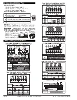
Step 3
Step 1
Operational Display
80
100
90
70
60
50
40
30
20
10
0
SP
SP
6
5
4
3
2
1
Press
at same
time
Press
at same
time
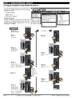
Enter Brightness Mode
80
100
90
70
60
50
40
30
20
10
0
SP
SP
6
5
4
3
2
1
80
100
90
70
60
50
40
30
20
10
0
SP
SP
6
5
4
3
2
1
Press
6
80
100
90
70
60
50
40
30
20
10
0
SP
SP
6
5
4
3
2
1
80
100
90
70
60
50
40
30
20
10
0
SP
SP
6
5
4
3
2
1
From Step 4
Step 4
Step 5
Exit Code 6.
Return to
Operational Display
Operational Display
80
100
90
70
60
50
40
30
20
10
0
SP
SP
6
5
4
3
2
1
80
100
90
70
60
50
40
30
20
10
0
SP
SP
6
5
4
3
2
1
Press
at same
time
Press
at same
time
80
100
90
70
60
50
40
30
20
10
0
SP
SP
6
5
4
3
2
1
Press
1
Step 2
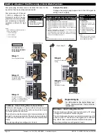
Pass Brightness Mode,
Calibration Mode, and
Codes 1 to 4 and enter
Code 5
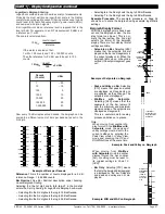
Set Code 5 to [11X]:
1st Digit = 1 Selects square root of CH3
2nd Digit = 1 Selects voltage, current
3rd Digit = X Not relevant
Save CH3 setting
X
CONFIGURE
CH3 FUNCTIONS
OR
0 Direct Display of Input
(no processing)
1 Square
Root
of
Channel 3
2 Inverse of Channel 3
3
4 kB Meters
32-point Linearization
of CH3 using Table 1
32 kB Meters
32-point Linearization
of CH3 using Table 3
Note:
All
linearization
tables are set up in
the Calibration Mode
[24X].
Code 5 is a single code that
combines all the configuration
and post processing functions
available for Channel 3.
When a
triple input
signal
conditioner is installed, the third
input signal is processed and
displayed on CH3.
Post processing and measure-
ment task functions for CH3 are
configured in the 1st, 2nd, and
3rd digits of Code 5. The
diagram opposite lists the avail-
able configuration selections in
Code 5.
FOR THERMOCOUPLE
0 Type J
1 Type K
2 Type R
3 Type S
4 Type T
5 Type B
6 Type N
7 Select user defined linearization
table (Table 1) set up in CAL [24X]
FOR RTD TYPE (2-, 3-, 4- WIRE)
0 Resistance
1 RTD 385
2 RTD 392
3 RTD 120
4 Cn 10
MEASUREMENT TASK
0 No Function
1 Voltage / current
2 TC (3rd digit selects type of TC)
3 RTD (3rd digit selects type of RTD)
4 Real Time Clock & Timer (3rd digit selects type)
5 -
6 -
7 Smart Input Module (3rd digit selects register)
CODE 5
–
CHANNEL 3 FUNCTIONS
FIRST DIGIT
SECOND DIGIT
THIRD DIGIT
CH3 POST PROCESSING
FOR REAL-TIME CLOCK & TIMER
0 HRS:MIN:SEC
1 HRS:MIN
2 -
3 -
4 1 Second Count UP Timer
5 1 Second Count DOWN Timer
6 -
7 -
FOR SMART INPUT MODULE
0 Output Register 1
1 Output Register 2
2 Output Register 3
3 Output Register 4
4 Output Register 5
5 Output Register 6
6 Output Register 7
7 Smart Input Module Register 2
Code Setup
P
Press
Use the
buttons to set the
required smart input module code
(0 to 377). See
I-Series Input
Modules Guide (Z87)
for code
details.
Example Procedure:
Configure CH3 to display the square root of a voltage
input by setting Code 5 to [
11X
].
ST
ST
AR
AR
T HERE
T HERE
I
n
i
ti
al
S
e
t
up P
r
o
c
e
du
r
e
s
[
C
o
d
E
_
5
]
-
C
h
a
nn
e
l
3
F
un
c
ti
o
n
s
See
I-Series Input Modules Guide (Z87)
for pro-
cedures to set up a triple input module.


