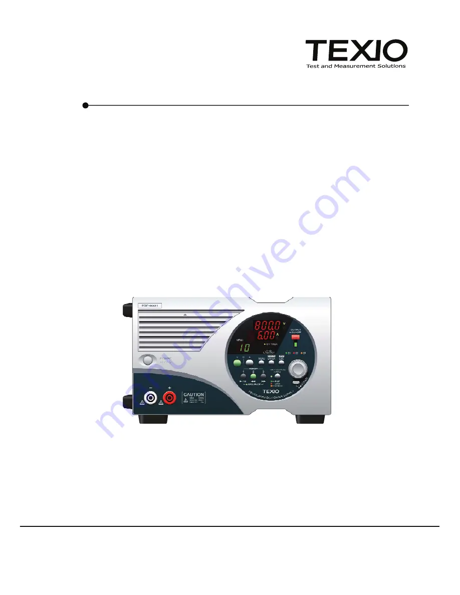
REGULATED DC POWER SUPPLY
PSF SERIES
PSF-400H
PSF-800H
©
PRINTED IN JAPAN B68-0166-00
INSTRUCTION MANUAL
Page 1: ...REGULATED DC POWER SUPPLY PSF SERIES PSF 400H PSF 800H PRINTED IN JAPAN B68 0166 00 INSTRUCTION MANUAL...
Page 2: ...respective companies or organizations in each country and region About the Instruction Manual Permission from the copyright holder is needed to reprint the contents of this manual in whole or in part...
Page 3: ..._________ 20 5 1 Connecting AC Power Cable 20 5 2 Connecting Load with Output Terminals 20 5 2 1 Connection with the rear output terminals 20 5 2 2 Assembling and connecting the front output terminal...
Page 4: ...ng external contacts 44 5 7 6 Various status signals CV CC ALARM 45 5 8 Activating output when turning on power 46 5 9 Usage of sequence Function 46 6 OTHER FUNCTIONS _________________________________...
Page 5: ...Off timer ON OFF TIMER MOD 68 8 8 13 Off timer value setting TIMER SET 68 8 8 14 Monitor inquiry MEAS 68 8 8 15 Preset calling PRES CALL 69 8 8 16 Preset saving PRES SAVE 69 8 8 17 Sequence mode sett...
Page 6: ...9 3 Function of the status byte 78 8 9 4 Reading data from the status byte and clearing the status byte 78 8 9 5 Clear and reset statuses 79 8 9 6 Remote local function 80 8 9 7 Responses to multi li...
Page 7: ...l may show this pictorial indication In this case if that part of the product is used incorrectly the user s body or the product may be exposed to serious danger Be sure to refer to this instruction m...
Page 8: ...t on source voltage over 125VAC Using the product on a high voltage that exceeds 125VAC without replacing the power cable may result in electric shock or fire For products that can switch between sour...
Page 9: ...fire Using Product Near Gases Do not use the product in or around a place where combustible gas explosive gas or vapor is produced or stored Failure to heed this warning may result in explosion or fi...
Page 10: ...tact our company or one of our service centers Daily Maintenance Do not use thinner benzine or other solvents to clean the case panels knobs etc of the product Doing so may cause the coating to peel o...
Page 11: ...out anything else It is possible to control the PSF Series from a Personal computer through the optional GP IB RS 232C or USB interface board The application software exclusive for the PSF series may...
Page 12: ...data read from a Personal computer through the optional interface board on the panel operation unit Two operation modes are available Manual mode for execution while checking the step details and auto...
Page 13: ...e Saving Design The frame depth is shorter than our other products for easy installation on a desk or other small space 1 4 Accessories Make sure the accessories are attached correctly If there are an...
Page 14: ...s subject to over shoot ringing etc Input Specifications Model PSF 400H PSF 800H Input voltage AC100V to 240V single phase frequency 50Hz or 60Hz Power consumption 3 560VA 1120VA Power factor 4 0 99 R...
Page 15: ...voltage 7 Measured at the frequency up to 20 MHz 8 Measured at the frequency up to 300kHz 9 Response time till the output voltage is restored to the range within 0 1 10 mV of the rated output voltage...
Page 16: ...oth ends of power supply Parallel one control operation Up to two units Preset function A maximum of three points are presettable Off timer OFF TIMER function Time until turning off output is presetta...
Page 17: ...rced cooling with fan motor To GND voltage DC1000V Dielectric strength voltage Power In terminals frame AC1500V 1min Power In terminals output terminals AC2300V 1min Insulation resistance Power In ter...
Page 18: ...200W Range 10W to 410W 20W to 820W Power setting Min display digit 1W SLOW 1V FAST 100V Range 10V to 840V OVP setting Min display digit 100mV SLOW 10mA 20mA FAST 1A 2A Range 0 1A to 3 15A 0 2A to 6 3...
Page 19: ...to 820W 20W to 1640W Power setting Min display digit 1W SLOW 1V FAST 100V Range 10V to 840V OVP setting Min display digit 100mV SLOW 10mA 20mA FAST 1A 2A Range 0 1A to 6 3A 0 2A to 12 6A OCP setting...
Page 20: ...N Preset function OFF Preset item Voltage 0V Preset item Current 0A Preset item Power 410W 820W Off timer function OFF Sequence function OFF Sequence start No 0 Sequence end No 99 Sequence repetition...
Page 21: ...re of grounding the unit may result in malfunctioning due to external noises and or increased noises generated by the unit Be sure to connect the GND terminal if a 2P 3P conversion plug is used owing...
Page 22: ...ned on the version data of the internal ROM are displayed the model name presence or absence of the interface address and other data are displayed and then the set voltage and current are displayed Pr...
Page 23: ...the Out position 2 Front output terminals Output is supplied through these terminals The maximum current is 3A 400H or 6A 800H 3 Front grill This is a ventilation grill for taking air for cooling the...
Page 24: ...mal operation Sequence operation Menu Alarm Current or power is displayed Step No is displayed Set item is displayed OVP OCP HARD or OHP is displayed The W LED on the right of the 7 segment LED is lit...
Page 25: ...The green LED is lit when the corresponding function is activated 13 Rotary encoder hereinafter merely referred to as encoder Used to select the functions and change the values 14 ROTATE key The pane...
Page 26: ...9 A key green Used for current setting Press the key and rotate the encoder to change the set value If the V key is pressed while holding the A key both LEDs are lit and the voltage 7 segment LED ente...
Page 27: ...ol from approx 0V to 800V at 0V to 10V in the external voltage control mode Control from approx 0V to 800V at 0k to 10k in the external resistance control mode 15 EXT CC CONTROL IN Constant current co...
Page 28: ...utput through these terminals On each terminal block the positive terminal is on the first and second pin at left side and the negative terminal is on the first and second pin at right side when the u...
Page 29: ...positive or negative output terminal of this unit An output ground cable should be used to ground the output terminal 29 AC INPUT Connect the AC power cable supplied with the unit with this plug rece...
Page 30: ...ver the grounding voltage 1000V for the load The front output terminals and rear output terminals are connected internally Even when the front output terminals are used there is still a risk of electr...
Page 31: ...ed at the negative terminal the load cables for external voltage control short circuits the output of the power supply unit resulting in troubles Use the power source for external voltage control in t...
Page 32: ...2 Use a 1 5 mm wrench to fasten the 2 screws 3 Insert the cover into the plug and make sure it hooks into place completion image 4 Turn off the power switch of the unit 5 Insert the above mentioned pl...
Page 33: ...of voltage and current setting within the rated power range than our traditional models Voltage setting range 0V to 800V All models Current setting range 0A to 3A PSF 400H 0A to 6A PSF 800H Power set...
Page 34: ...nd the panel operation unit is locked To return the unit to its original position hold the encoder and turn it counterclockwise 90 degrees while pressing down the ROTATE key Be sure to confirm that th...
Page 35: ...ress the A key which is then lit in green If not press the A key to turn it on 2 Set an intended value with the encoder 5 4 5 How to set power Operation procedure 1 Press the V key while pressing and...
Page 36: ...nction See Section 5 5 6 External control ON OFF 06 below 1 Turning output on or off using the OUTPUT key Operation procedure 1 Press the OUTPUT key which is then lit in red The output of the PSF seri...
Page 37: ...dicating that the set value is being displayed The set value is changed if the encoder is rotated in the setting mode The output value is changed if the encoder is rotated in the output mode Do not to...
Page 38: ...ms Illustrations in the descriptions below represent the following Operation procedure 1 Press the MENU key until an intended function number is displayed 2 Press the ENTER CHECK key to validate the f...
Page 39: ...ration procedure Set the voltage current and power following the step in 5 4 3 How to set voltage 5 4 4 How to set current 5 4 5 How to set power 1 Press the MENU key until menu number 01 is displayed...
Page 40: ...setting range is from 0 10A to 3 15A 400H 6 30A 800H The resolution is 0 01A The resolution is different in one control parallel operation See Section 2 SPECIFICATIONS Operation procedure 1 Press the...
Page 41: ...ng mode 3 Select ON or OFF with the encoder The Off Timer is set to OFF before shipment 4 Press the ENTER CHECK key to validate setting Select ON The OFF timer indicator is then lit in green 5 Then se...
Page 42: ...from our homepage Operation procedure 1 Press the MENU key until menu number 04 is displayed 2 Press the ENTER CHECK key to enter the OFF timer setting mode 3 Select ON or OFF with the encoder The Of...
Page 43: ...idate it 9 Set the number of times of repeating the steps with the encoder The setting range is from 1 to 999 plus infinite 10 Press the ENTER CHECK key to validate it How to set the number of times o...
Page 44: ...ginning with Step 20 If output is active at the end of the program as shown in Fig 5 8 the power supply unit remains in the status of the last step even after completion of sequence operation Output s...
Page 45: ...o control the voltage of the PSF Series power supply unit by connecting an external resistance with the unit The output voltage is controlled from approximately 0V to approximately 800V output voltage...
Page 46: ...ment 4 Press the ENTER CHECK key to validate it 5 Press the ENTER CHECK key to select CV Set voltage CC Set current V W A W V W A W 6 Select objective of external control with the encoder IN Control o...
Page 47: ...ee Section 5 7 4 Output ON OFF with external contacts below Operation procedure 1 Press the MENU key until menu number 07 is displayed 2 Press the ENTER CHECK key to validate it 3 Select ON or OFF wit...
Page 48: ...n the unit while holding the MENU key Menu number 10 is displayed Select an intended operation mode with the encoder Initial setting Master unit in parallel connection 2 Slave unit in parallel connect...
Page 49: ...nect an electrolytic capacitor of several hundred F to several thousand F to the load terminals 1 Make sure that the POWER switch is off before starting work 2 Disconnect the wire that short circuits...
Page 50: ...2B 7006 OMRON manufacture to attach the wire and enhance its reliability Wires suitable for use are AWG 28 AWG 26 and AWG 24 stranded wire with a sheath outer diameter of 1 1 mm to 1 3 mm 3 Reinsert t...
Page 51: ...nt of the PSF H Series power supply unit in voltage The internal impedance of the voltage and current monitoring circuits is approximately 1k Be careful not to flow current over 1mA through the monito...
Page 52: ...er supply unit Use the external voltage source in the floating condition to avoid accidents or malfunctioning If the external resistor is disconnected for some reason in the external control mode exce...
Page 53: ...through the connector J3 EXT CONT on the rear panel if external control is selected in Section 5 5 5 External control external voltage external resistance 05 above For the setting procedures see Sect...
Page 54: ...5 26 EXT CONT J3 Negative output Fig 5 12 Output ON OFF Terminals with External Contacts 5 7 5 Alarm function using external contacts It is possible to bring the PSF Series power supply unit into the...
Page 55: ...status Alarm status signal This status signal goes Low when the PSF H Series power supply unit enters the alarm status Refer to the specification table below for details about the photo coupler PC3H7...
Page 56: ...or the procedures of setting the sequence operation Download the application software exclusive for the sequence operation from our homepage and create sequence programs in advance 1 Write sequence pr...
Page 57: ...quence operation is different from that in normal operation It is as shown below When the ESC DISP key is pressed in sequence operation the step number is displayed on the voltage 7 segment LED and th...
Page 58: ...OCP function 02 Turn off the input power source or shut off the POWER switch and throw it again to reset the protection function Type of alarm Display Description OVP alarm This alarm code is displaye...
Page 59: ...it When the OUTPUT key of the master unit is thrown outputs of the slave units are turned on automatically Improper wiring or setting may cause failures Recheck the setting before starting one control...
Page 60: ...50 Load grounding grounding OUT OUT Master unit F G Frame ground J1 J2 Slave unit 1 OP 22P S OUT OUT S OUT OUT J1 J2 S OUT OUT S F G Frame ground Fig 6 1 Parallel Connection...
Page 61: ...ead screws supplied with the kit Four positions 3 Place the units as shown in Fig 6 2 below so that the projections of the JK 10 on the unit B are inserted in the holes in the unit A from which the ru...
Page 62: ...its as shown in Fig 6 3 below so that the projections of the JK 10 on the unit B are inserted in the holes in the unit A from which the rubber shoes are removed above 4 Shift the unit A and fix the re...
Page 63: ...e available for the PSF Series power supply unit JK 10 Joint kit HK 10 Handle kit OP 22P Parallel signal cable 7 2 Interface Boards Two types of optional interface boards shown below are available 1 I...
Page 64: ...These boards enable a maximum of ten units to be connected with the master unit connected with a Personal computer through a local bus The connected units may be controlled as the slave units The ter...
Page 65: ...n Q ty of connectable units One to one connection only USB section Specifications Specifications Connector type Connector type Device class Device class Vendor code Vendor code Product code Product co...
Page 66: ...d presence or absence of responses are reported Q ty of connectable units Maximum of 14 units are connectable with a single GP IB card Local bus section Specifications Conforms to the RS 485 Standards...
Page 67: ...utput of the interface board need not be discriminated for local bus connection Use as short modular cables as possible Short circuit the jumper pins CN2 of the interface units at both ends with the s...
Page 68: ...ected with a Personal computer or a slave unit connected with the local bus If the system address of a unit is set to 1 that unit serves as the master unit whose Personal computer address may be speci...
Page 69: ...r to select the proper address 3 Press the ENTER CHECK key The selected system address is validated A unit whose system address is other than 1 provides normal operation When the system address 1 is s...
Page 70: ...60 Use the IF 60RU in the master unit when the USB interface is used Fig 8 3 Address Setting Example using GP IB Interface...
Page 71: ...may download the sample programs from the Texio homepage Access to http www texio jp 2 SendADDR1 See Section 8 8 32 Local address setting ADDR below 8 7 2 Using the USB interface You may use the USB...
Page 72: ...careful 8 8 Communication commands Every communication command consists of general alphanumeric characters and symbols and has a header which is the abbreviation of a function Parameters consist of an...
Page 73: ...N OFF TIMER MOD TIMER MOD 68 31 Off timer Off timer value setting TIMER SET TIMER SET 68 31 Status check Monitor request MEAS 68 41 Call PRES CALL PRES CALL 69 29 Preset Save PRES SAVE PRES SAVE 69 29...
Page 74: ...is valid Application example VOLT PROT 101 0 Sets the OVP voltage 101 0V Query VOLT PROT Inquires about the set OVP value Response example 101 0 Indicates that the set OVP value is 101 0V Remark None...
Page 75: ...ion example CURR PROT 1 01 Sets the OCP value 1 01A Query CURR PROT Response example 1 01 Indicates that the set OCP value is 1 01A Remark None 8 8 5 Output power setting POW This command sets or inqu...
Page 76: ...cts the voltage current display mode Query CONF DISP Inquires about the display setting Response example 1 Indicates that the voltage current display mode is selected has the same function as value Re...
Page 77: ...w 0 Deactivates external output current control for control from the panel or through communication 1 Activates external output current control Application example EXT CURR 1 Selects the external outp...
Page 78: ...r part and minutes in the first decimal place in units of 10 minutes Applicatuin example TIMER SET 10 3 Set the Off Timer value to 10 hours and 30 minutes Query TIMER SET Inquires about the setting Re...
Page 79: ...PRESET memory PRES SAVE value Setting value is as shown below 1 Saves the current set value in PRESET 1 2 Saves the current set value in PRESET 2 3 Saves the current set value in PRESET 3 Application...
Page 80: ...8 8 19 Sequence start step setting SEQ START This command specifies a start step of sequence operation SEQ START value Setting The value range is from 0 to 99 Application example SEQ START2 Sets the s...
Page 81: ...ents 1609 byte binary sequence set data Application example SEQ DOWNLOAD 6001600 LF Transfers the 8 byte header of the binary data 1600 byte actual data and delimiter data in sequence Query SEQ DOWNLO...
Page 82: ...er setting SRE The function of this command is described in Status register in the following section 8 8 28 Buffer clear CLS This commnd clears the buffers Setting CLS Clears the send buffer receive b...
Page 83: ...ccepts overlap commands only Executes no processing in particular Query None 8 8 32 Local address setting ADDR This command specifies the address of a slave unit on the local bus ADDR value Setting Th...
Page 84: ...ote status 2 Local lockout remote status Cannot return to the local status through key operation Application example REMOTE0 Sets the local status Query REMOTE Response example 1 Indicates that the un...
Page 85: ...75 8 9 Registers The PSF power supply unit has registers that conform to the status reporting specified in IEEE488 2...
Page 86: ...excluding this bit bit 6 and the service request enable register is 1 RQS is set to 1 when MSS changes from 0 into 1 It is cleared when MSS is cleared or serial polling is executed ESB Indicates that...
Page 87: ...ution error 0 0 3 8 ALM Alarm occurrence 0 0 2 4 Unused 0 0 1 2 Unused 0 0 0 1 OPC Operation complete 0 0 Item Description Sets or inquires about the standard event status enable register Setting comm...
Page 88: ...te and clearing the status byte Data of the status byte may be read out from the controller in the following two ways Inquiry with the STB query When an inquiry is made with the STB query MSS is read...
Page 89: ...tus is cleared The SRQ and status byte are cleared The remote status and LLO setting are cleared and the power supply unit enters the local state Panel setting remains unchanged RST Reset command Resp...
Page 90: ...mode where any other panel keys than the POWER switch and FAST key are inoperative In the local lockout status any other keys than the POWER switch are inoperative with the only exception of an error...
Page 91: ...ressed The set voltage is 0V The set current is 0A In the CC status On Off with the external contacts is selected Keys are locked See Section 5 4 3 How to set voltage See Section 5 7 2 Set voltage wit...
Page 92: ...ssing the notch in the upper part to detach the grill Clean the filter with water Before starting cleaning shut off the POWER switch without fail and disconnect the AC power cable to turn off the unit...
Page 93: ...83 11 OUTSIDE DIMENSIONS 209 9 10 9 124 290 12 5 1 The handle is available by option Fig 10 2 Outside Demension of PSF H...
Page 94: ...1850 1 Tsuruma Machida shi Tokyo 194 0004 Japan http www texio jp...