↓
The “
↓
” button scrolls down through the menu. The “
↓
” button
is also used confirm certain commands, as indicated on the
display. If the menu is not selected, this button is disabled.
3.1.1
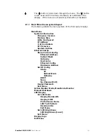
Front Panel menu system layout
The following details the menu system of the front panel display:
Main Menu
System Information
Firmware
Version
Memory
Size
LUNs
Configured
IP
Address
# of Controllers
FC
Firmware
System
Uptime
Ethernet Setup
Show Current Config
Ethernet
Address
Subnet
Mask
Gateway
Hostname
Ethernet
Config
Hardware
Address
Set IP Config
Static
IP
Subnet Mask
Gateway
DHCP
None
No Change (Exit)
Restart Network
Exit Menu
Active Monitor Mode/Deactivate Monitor
Manual Shutdown
LED
Display
Set LED Mode
Display Bandwidth
Display IOPS
Performance Demo
LED Test Pattern
Disable LEDs
Exit
Menu
Set
LED
Brightness
LED Brightness [Level]
Exit
Menu
Display logo
Exit Menu
RamSan-300/320/325
User’s Manual
- 14 -
Summary of Contents for 320
Page 1: ...TEXAS MEMORY SYSTEMS INC RamSan 300 320 325 User s Manual Version 2 1 ...
Page 12: ...Figure 2 1 RamSan 320 325 Layout RamSan 300 320 325 User s Manual 8 ...
Page 110: ...Figure B 3 Power Supply Module Figure A 5 Memory Blade RamSan 300 320 325 User s Manual 106 ...
Page 111: ...Figure A 6 120 Gigabyte Replacement Hard Drive RamSan 300 320 325 User s Manual 107 ...


