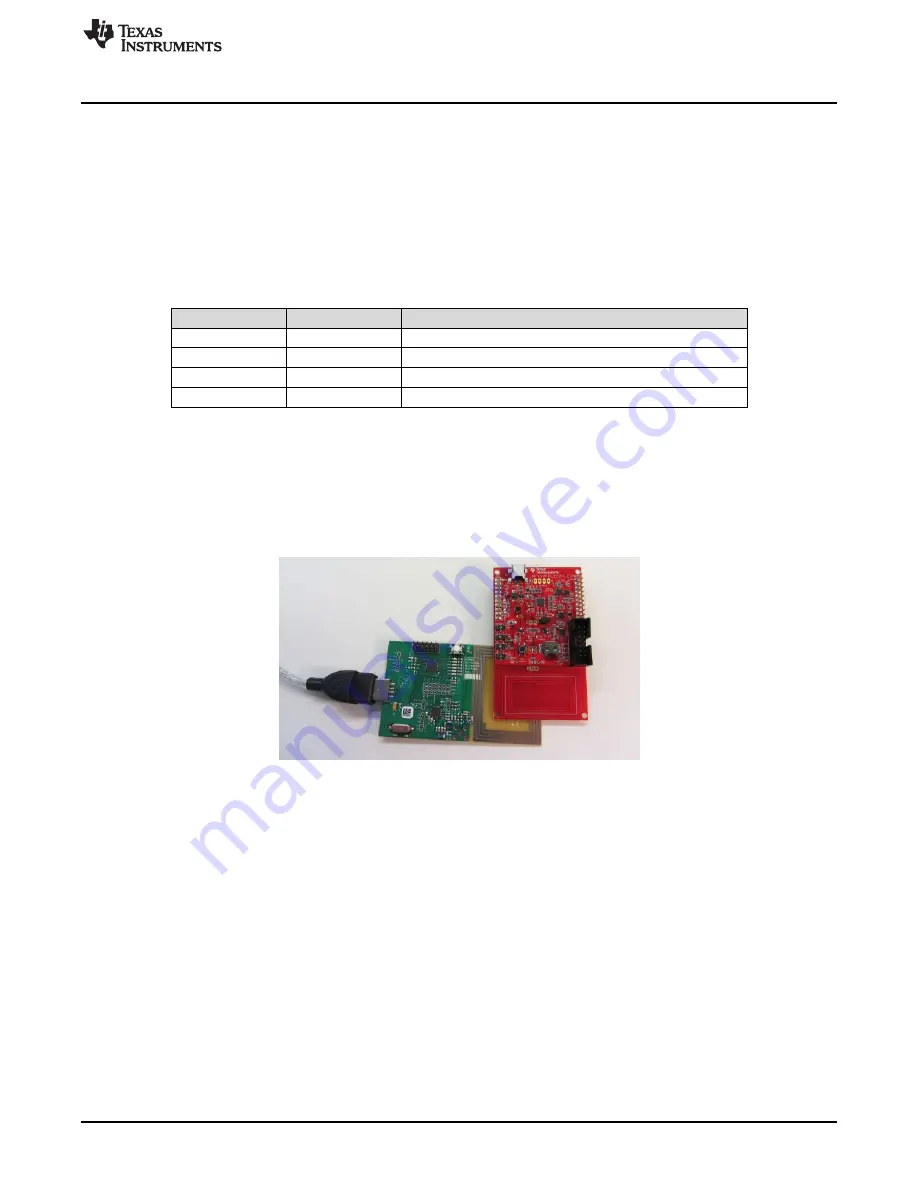
Setup of Demo System
5.2
Set up the RF430FRL152HEVM Demo Using the PC
This section describes how to setup and run the sensor demo. With this setup, the RF430FRL152HEVM
samples, using the onboard ADC, two external sensors, the thermistor and the light sensor. After
collecting the samples, the data is transmitted over RF to the TRF7970AEVM which reports them to the
PC application. Finally the results are plotted on the graphs. In this demo the RF430FRL152HEVM is run
completely wireless, with no power or data connections.
1. Connect the TRF7970AEVM to the PC with a USB cable.
2. On the RF430FRL152HEVM, use a pen or pencil to set the mini-switches as shown in
Table 3. Switch Positions For Passive Operation
Switch ID
Position
Comment
S6
Battery
There is no need for a battery to be present
S5
0
Does not matter what state this switch is in
S4
0
Does not matter what state this switch is in
S3
S
Device starts in I
2
C/SPI slave mode
3.
The RF430FRL152HEVM should not be connected to a USB cable for this demo
. If it is
connected, set switch S6 to the "Supply" position. The rest of the steps are the same.
Note: If EnergyTrace technology is used, a USB cable should not be used and the EVM must be
powered from the MSP-FET tool.
4. Position the RF430FRL152HEVM antenna on the antenna portion of the TRF7970AEVM as shown in
. It is recommended to have an insulator between the two antennas or to hold them at a
distance from each other to prevent any short circuits.
Figure 15. Position the EVMs
5. Open the RF430FRL15xH GUI Interface application by going to the Start menu
→
All Programs
→
Texas
Instruments
→
RF430FRL152H GUI .
6. Press the "Connect to TRF7970AEVM" button on the bottom of the window.
7. A few seconds after you click the "Connect" button, the label next to the button should show
"Connected to TRF7970AEVM on COMx".
If this is not displayed, then a connection has not been made. In this case, disconnect the
TRF7970AEVM and reconnect it, then restart at step 1. If this still does not solve the problem, make
sure that the TRF7970AEVM has the latest firmware downloaded from the TRF7970AEVM tool folder.
8. In the "Setup Tab" select the "Without Sensor Hub BoosterPack" and "RF430FRL152HEVM" options.
9. Go to the "Demo Mode" tab.
10. Click the "Start Demo" button.
11. The GUI starts to plot the temperature and light intensity samples on the graphs.
(a) To plot these values, the PC GUI configures the RF430FRL152HEVM through the TRF7970AEVM
to take two different samples from the analog thermistor and light sensors.
(b) When the samples are complete, the PC GUI reads the result from FRAM of the
21
SLAU607 – December 2014
RF430FRL152HEVM User's Guide
Copyright © 2014, Texas Instruments Incorporated


