


C5535 DSPShield H/W Reference Manual
Version 0.1
In Collaboration with Stanford University
page
7
If either voltage drops below certain thresholds, the TPS65001’s active low open-drain
reset output will go low and reset the C5535 DSP and the DSPShield.
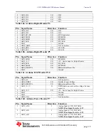
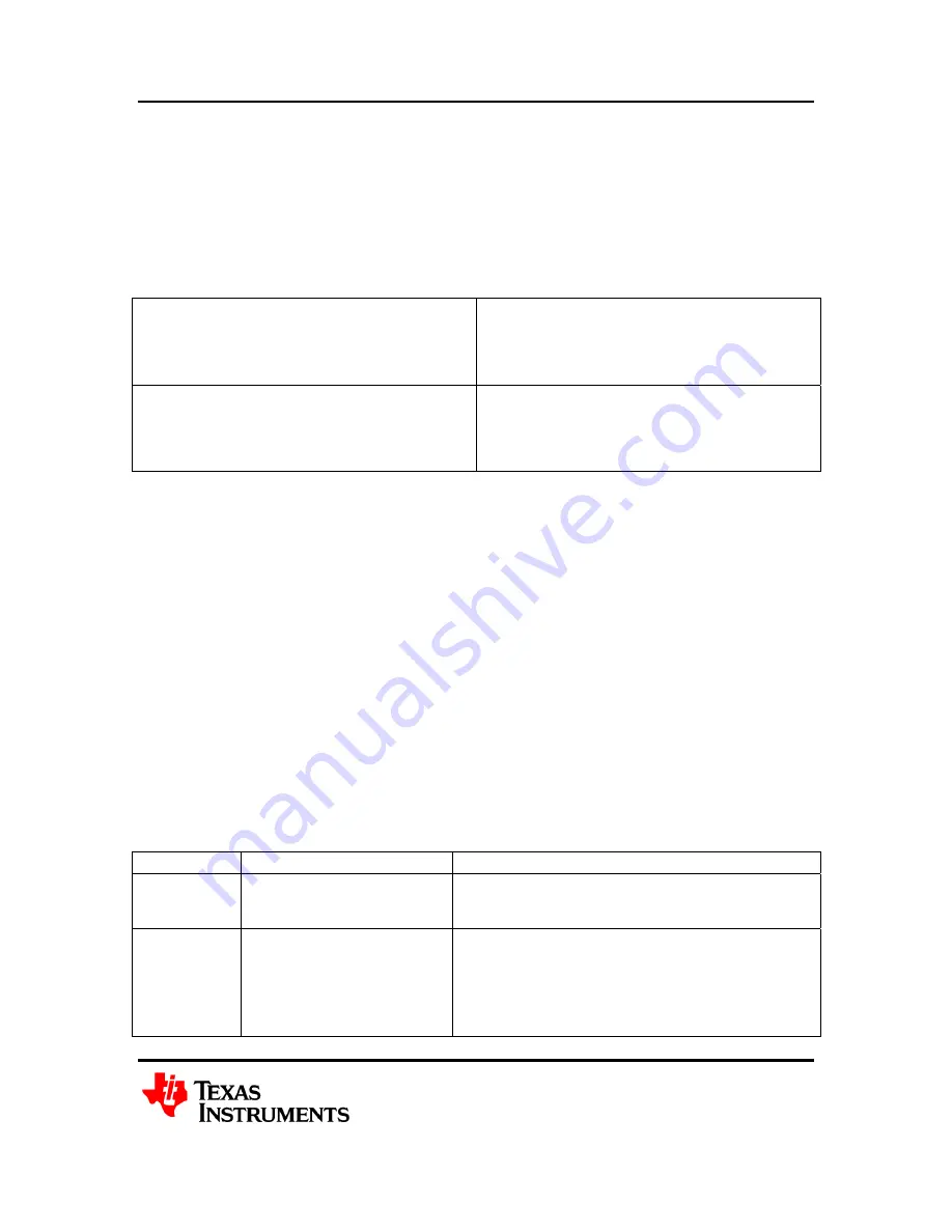
2.4 C5535 DSP Core Voltage
The C5535 DSP’s +1.3V Core Voltage, CVDD, can be driven either by its internal LDO
or by the LP3982 LDO. The selection is accomplished by populating certain
combinations of resistors R25, R26, R27 and R28. The two options are listed in Table 5.
CVDD = C5535 DSP_LDOO
(
DEFAULT )
R25 = DNI
R26 = 0 Ohm Resistor
R27 = 0 Ohm 1/8W Resistor
R28 = DNI
CVDD = LP3882 LDO
R25 = 10.0K Ohm Resistor
R26 = DNI
R27 = DNI
R28 = 0.0 Ohm 1/8W Resistor
Table 4. C5535 DSP Core Voltage Selection
3 C5535 DSP and Internal Peripherals
The C5535 DSP is a high-performance, low-power, fixed-point Digital Signal Processor.
It has dual multipliers, dual ALUs, and a tightly coupled FFT hardware accelerator for
performing math intensive signal processing algorithms. It has a multiple I/O peripherals
that allow it to easily connect to serial Analog to Digital Converters, Digital to Analog
Converters and integrated codecs.
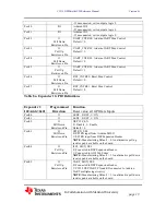
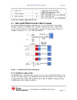
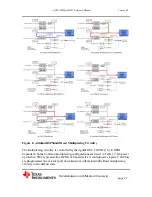
3.1 Parallel and Serial Peripherals
The C5535 DSP’s internal External Bus Selection Register (EBSR) determines which of
the following: LCD controller, I2S0, I2S1, I2S2, I2S3, UART, SPI, MMC/SD and GPIO
signals appear at the chip’s multiplexed GPIO pins. These peripherals can be grouped
into 3 groups as shown in Tables 5a, 5b and 5c. For each group, only one mode of
operation is available at a given time. Note that the DSPShield architecture further limits
the group mode selection.
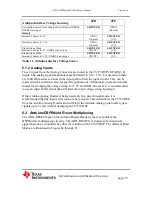
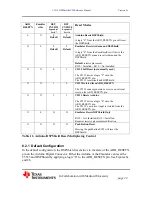
PP MODE Multiplexed I/O
Board Level limitations
Modes
0,2,3,4,5
-
Not Supported
Mode 1
SPI/I2S2/UART/6 GPIO
Fully Supported.
-
I2S2 multiplexed between AIC3204 and DSP
Expansion Connector.
-
UART multiplexed between Arduino, XDS
Serial Port and DSP Expansion connector.
-
SPI multiplexed between Arduino and DSP


