

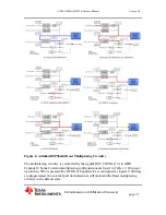


Figur
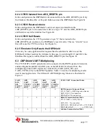
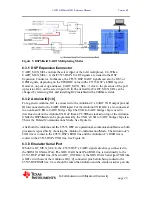
6.3.1
UAR
UAR
Expa
GPIO
Howe
up re
chang
6.3.2
For a
IO0 i
to an
down
UNO
This
After
proce
TXD
route
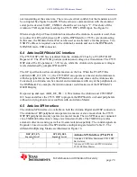
6.3.3
When
the X
C553
is OR
C553
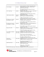
re 9. DSPSh
1 DSP Ex
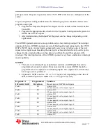
RT_MUX_SE
RT_MUX_SE
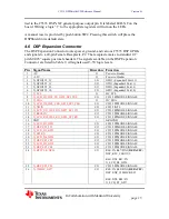
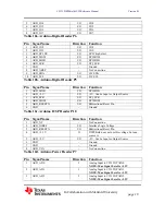
ansion Conne
O signals, de
ever, on pow
sistor, R41,
ged by remo
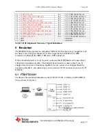
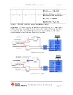
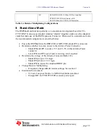
2 Arduino
a generic Ard
is connected
onboard US
nload code to
O, the DSPSh
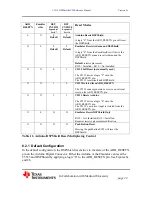
is the Defau
r both the Ar
essors is pos
line is route
d to the C55
3 Emulato
n UART_MU
XDS JTAG S
35 DSP’s TX
R’ed with on
35 DSP RXD
C553
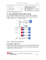
hield UART
xpansion C
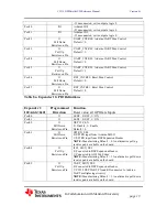
EL controls t
EL = 0, the C
ector. In this
pending on t
wer up and re
on the selec
oving R41 an
o IO[1:0]
duino, IO1 is
to the UAR
SB to UART
o the Arduin
hield can be
ult Communi
rduino and th
sible by cho
ed to the C55
535 DSP’s T
or Serial P
UX_SEL=0
Serial Port. T
XD line. Whe
ne of the Ard
D line. Care s
35 DSPShield H/
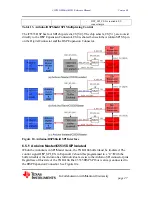
In Collabo
T Multiplexi
Connecto
the select inp
C5535 DSP’
s case, the C5
the PPMOD
eset, UART_
t input of U4
nd installing
s connected
RT RXD inpu
T bridge chip
no UNO uC f
programmed
ications Mod
he C5535 DS
osing the Ar
535 DSP’s R
TXD line. Se
Port
, the C5535
The XDS JTA
en UART_C
duino’s IO[1
should be ta
/W Reference M
oration with S
ing Modes
r
put of the 4-
’s UART sig
5535 DSP U
DE value in th
_MUX_SEL
4. The defau
R42 installe
to the Ardui
ut. For the A
p. The USB t
from a PC. W
d by the UN
de. See Figu
SP are opera
rduino Comm
RXD line and
e Figure 8b.
DSP’s UAR
AG Serial Po
CNTRL0=0,
:0] connecto
ken that Ard
Manual
Stanford Un
-bit multiple
gnals are rou
UART signal
he C5535 D
L = 1 due to
ult for UART
ed with a 0 O
ino uC’s UA
Arduino UNO
to UART bri
When stacke
NO’s USB to
ure 8a
ational, comm
munication M
d the Arduin
RT signals ar
ort RXD lin
the XDS JT
or pins befor
duino and th
niversity
exer, U4. Wh
uted to the D
ls can also b
SP’s ESBR
the presence
T_MUX_SE
Ohm resistor
ART TXD ou
O, IO0 is als
idge chip is
ed on top of
UART brid
munication b
Mode. The A
no uC’s RXD
re always co
ne is tied dire
TAG Serial p
re being rout
he emulator s
Version 0.1
page
25
hen
SP
e I2S3 or
register.
e of the pull
EL can be
r.
utput pin and
o connected
used to
the Arduino
dge chip also
between bot
Arduino uC’
D line is
onnected to
ectly to the
port TXD lin
ted to the
serial port ar
1
d
d
o
o.
th
’s
ne
re


